EXBOX.RAV User‘s Manual Version 1.
Copyright All rights reserved. Permission to reprint or electronically reproduce any document or graphic in whole or in part for any reason is expressly prohibited, unless prior written consent is obtained from the DirectOut GmbH. All trademarks and registered trademarks belong to their respective owners. It cannot be guaranteed that all product names, products, trademarks, requisitions, regulations, guidelines, specifications and norms are free from trade mark rights of third parties.
Table of contents About This Manual 5 How to Use This Manual................................................................................ 5 Conventions................................................................................................... 5 Chapter 1: Overview 6 Introduction.................................................................................................... 6 Feature Summary...........................................................................................
CHAPTER 5: Remote Control 30 Introduction.................................................................................................. 30 Browser Control........................................................................................... 32 Status - Overview......................................................................................... 33 Status - Sync................................................................................................ 34 Status - Network.................
About This Manual About This Manual How to Use This Manual This manual guides you through the installation and operation of the device. Use the Table of Contents at the beginning of the manual or Index Directory at the end of the document to locate help on a particular topic. You can access more information and latest news by visiting on the DirectOut website at www.directout.eu. Conventions The following symbols are used to draw your attention to: TI P S indicate useful hints and shortcuts.
Chapter 1: Overview Chapter 1: Overview Introduction EXBOX.RAV is an Audio-over-IP to MADI converter based on the audio networking technology RAVENNA. Equipped with three MADI ports and four network ports it offers straight-forward conversion of 64 audio channels between MADI and RAVENNA. Two independent NICs can be connected to four network ports of the built-in switch, supporting redundant audio streaming as per ST 2022-7. page 6 of 93 EXBOX.RAV Manual - Version 1.
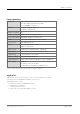
Chapter 1: Overview Feature Summary MADI Ports 1 x SC multi-mode connectors * 1 x SFP (empty cage without module) 1 x coaxial BNC connectors Network 3 x RJ45 Socket (1 Gbit/s), 1 x RJ45 (1 Gbit/s, PoE) Number of streams 32 Number of channels 64 @ 1 FS, 32 @ 2 FS, 16 @ 4 FS Network Standards RAVENNA, AES67, ST 2110-30 / -31 Modes Switched or Redundancy as per ST 2022-7 Clock Sources PTP, MADI, WCK, INT Remote Browser GUI, globcon control, NMOS IS-04 / IS-05 MADI Formats 56/64 channel, 48k/9
Chapter 1: Overview How it works Each MADI port and the RAVENNA input can be selected as source for any output. A FastSRC™ can be enabled for seamless exchange of audio signals with the RAVENNA network if the device is not clocked to the audio network. The network audio is controlled via the brower based user interface or globcon or via an NMOS controller. SFP BNC SC SFP Routing EXBOX.RAV BNC SC FSRC RAVENNA Routing Audio Network RAVENNA About FastSRC™ - see page 26. page 8 of 93 EXBOX.
Chapter 1: Overview This page is left blank intentionally. EXBOX.RAV Manual - Version 1.
CHAPTER 2: Legal issues & facts CHAPTER 2: Legal issues & facts Before Installing This Device WAR NING! Please read and observe all of the following notes before installing this product: • Check the hardware device for transport damage. • Any devices showing signs of mechanical damage or damage from the spillage of liquids must not be connected to the mains supply, or disconnected from the mains immediately by pulling out the power lead. • All devices must be grounded.
CHAPTER 2: Legal issues & facts First Aid (in case of electric shock) WA R N I N G ! • Do not touch the person or his/her clothing before power is turned off, otherwise you risk sustaining an electric shock yourself. • Separate the person as quickly as possible from the electric power source as follows: - Switch off the equipment. - Unplug or disconnect the mains cable. • Move the person away from the power source by using dry insulating material (such as wood or plastic).
CHAPTER 2: Legal issues & facts Updates DirectOut products are continually in development, and therefore the information in this manual may be superseded by new releases. To access the latest documentation, please visit the DirectOut website: www.directout.eu. This guide refers to firmware version 1.6.3 and AoIP module version SW 0.17 / HW 0.46. Intended Operation EXBOX.RAV is designed for conversion / routing between network audio and MADI signals.
CHAPTER 2: Legal issues & facts Conformity & Certificates CE This device complies with the basic requests of applicable EU guidelines. The appropriate procedure for approval has been carried out. RoHS (Restriction of the use of certain Hazardous Substances) This device was constructed fulfilling the directive on the restriction of the use of certain hazardous substances in electrical and electronic equipment 2011/65/EU and 2015/863.
CHAPTER 2: Legal issues & facts Contents The contents of your EXBOX.RAV package include: • 1 x EXBOX.RAV • 1 x external power supply unit (9 - 24 V) • 1 x Instruction Leaflet Remote Control The device can managed either via web control in a browser or via globcon remote control. globcon is a free, global control software platform for the management of professional audio equipment. Almost all products of the DirectOut product portfolio are supported by globcon. Link: www.globcon.pro page 14 of 93 EXBOX.
CHAPTER 2: Legal issues & facts Accessory Two different optical SFP transceiver for MADI transmission are available from DirectOut GmbH: • Multimode SFP transceiver with LC connectors (No: DOICT0129) • Singlemode SFP transceiver with LC connectors (No: DOICT0130) Specification of the optical SFP modules: SFP Multimode Singlemode Wavelength TX 1310 nm 1310 nm Wavelenght RX 1310 nm 1310 nm Distance 2 km 10 km Powerbudget (dB) 11 dB 12 dB Protocols Fast Ethernet OC3/STM1 Gigabit Ethernet, Gig
CHAPTER 2: Legal issues & facts BOXMOUNT XL - for optimal rack mount of up to three devices in a 19’’ frame (No: DOAPA0886): page 16 of 93 EXBOX.RAV Manual - Version 1.
Chapter 3: Installation Chapter 3: Installation Installing the Device 1. Open the packaging and check that the contents have been delivered complete and undamaged. 2. Place the device on a non-slip horizontal surface. The delivered pads may be affixed to the bottom of the cabinet. Ensure a clean and dry surface before affixing the pads. WA R N I N G ! The synthetics of the delivered pads might cause stains on damageable surfaces.
Chapter 3: Installation 4. Connect signal cable(s) for the MADI signals. 5. Plug in the network cable to the ethernet port(s) to connect the device with your computer. Default network configuration: • Use Port 1 for access via 192.168.0.1 • Use Port 2 for access via DHCP NOT E Use appropriate network cables (CAT5E or better). page 18 of 93 EXBOX.RAV Manual - Version 1.
Chapter 3: Installation 6. Using the power cord of the external power supply provided, connect the device to a matching power supply and connect the output of the power supply to the Hirose connectors at the rear panel. This device may operate with only one power supply. To provide power supply redundancy, it is recommended to connect both PSU 1 and PSU 2 to independent power supplies with separate fuses. N OT E The shipment includes one external power supply unit.
Chapter 3: Installation Power over Ethernet The device can also be operated via a power over ethernet connection. Connect the port labelled '01 (PoE)' to an appropriate PoE switch (PoE Class 0 / 0.4 - 13 W, IEEE 802.3af). WAR NING! Never connect a PoE link to a network interface that is not marked explictly for PoE operation. The voltage supplied there may damage the interface. T IP Keep any packaging in order to protect the device should it need to be dispatched for service. page 20 of 93 EXBOX.
CHAPTER 4: Operation CHAPTER 4: Operation Introduction This chapter describes the basic operation of the device. Note that throughout this manual, the abbreviation FS refers to sample rate or sample frequency. So, when dealing with scaling factors, the following sample rates can be written as: • 44.1 kHz or 48 kHz = 1 FS • 88.2 kHz or 96 kHz = 2 FS • 176.4 kHz or 192 kHz = 4 FS EXBOX.RAV Manual - Version 1.
CHAPTER 4: Operation Global Control PSU 1 Hirose socket Connect the power supply here (9 - 24 V DC). PSU 2 Hirose socket Connect the power supply here (9 - 24 V DC). 01 (PoE) RJ45 socket Connect PoE link here. PoE Class 0 / 0.4 - 13 W NOT E The device does not provide a power switch. Connecting a working power supply to the device will power up the device immediately. WAR NING! Never connect a PoE link to a network interface that is not marked explictly for PoE operation.
CHAPTER 4: Operation Input / Output - MADI Three different MADI ports enable flexible connectivity in various scenarios. Due to the device's routing capabilities format conversion between different MADI formats is possible. MADI BNC OUT BNC socket MADI output - connect here for MADI output signal. MADI BNC IN BNC socket* MADI or WCK input - connect MADI or word clock input signal here. MADI SC OUT SC socket MADI output - connect here for MADI output signal.
CHAPTER 4: Operation Input / Output - Network Four network ports are available for transmission of audio signals and remote control. Two independent network interface controllers (NICs) can connect with each of the four network ports of the built-in switch. More details about the switch configuration - see page 77. 01 (PoE) RJ45 socket (1 Gbit/s) Network interface - connect here for network transmission. This port accepts a PoE source for power supply - see page 22.
CHAPTER 4: Operation Input State / Clocking Five LEDs inform about the state of each signal input and the selected clock source of the device. The device ofers several options for clocking: • PTP (Precision Time Protocol) - IEEE 1588-2002 / PTPv2 • MADI input • Word Clock (@ MADI BNC input)* • internal clock generator CLOCK SOURCE / SYNC SFP BNC* SC PTP INT LED - indicates selected clock source and the lock / sync state of MADI input, PTP-clock or the internal clock generator.
CHAPTER 4: Operation Sample Rate Conversion A switchable sample rate converter is available for the audio network I/O. This is helpful if the device can't be clocked to the audio network (or act as grandmaster). The FastSRC™ is a low latency sample rate converter and ensures seamless exchange between MADI and RAVENNA I/O when both sources are not synchronised. It is either switchable in the EXBOX Remote or in globcon. SFP BNC SC SFP Routing EXBOX.
CHAPTER 4: Operation Clocking to word clock The BNC MADI input also accepts a word clock signal according to AES11. The operating mode of the BNC input is selected in the Remote control - see p 36. CLOCK SOURCE / SYNC BNC LED - indicates selected clock source and the lock / sync state of MADI BNC / WCK input.
CHAPTER 4: Operation Sample Rate The base rate (44.1 kHz, 48 kHz) and the scaling factor (1 FS, 2 FS, 4 FS) is displayed by four LEDs at the front panel. NOT E At higher sample rates the number of audio channels is reduced depending on the integer of the scaling factor: • 64 channels at 1 FS • 32 channels at 2 FS • 16 channels at 4 FS page 28 of 93 SAMPLE RATE 44.1k LED green - indicates the base rate of the audio engine. (OFF) = base rate is different from 44.1 kHz (ON) = base rate of 44.
CHAPTER 4: Operation State The status of the RAV2 module is monitored by a LED at the front. STATE LED blue - indicates the state of the RAV2 module. (OFF) = module not available (ON) = module is working (blinking) = module in failsafe mode* * The RAV2 module starts into failsafe mode if its firmware is corrupted. This may happen in very rare cases only. Should you encounter this state, please contact support for further information. EXBOX.RAV Manual - Version 1.
CHAPTER 5: Remote Control CHAPTER 5: Remote Control Introduction EXBOX.RAV can be controlled via a browser based interface and globcon (partially). For control via 3rd party devices NMOS IS-04 (stream and device discovery) and IS-05 (connection management) are supported. Browser interface The size of the window and the zoom level can be varied. The page is organized in tabs, pulldown menus or hyperlinks offer access to the values of a parameter. Some values use an input field (e.g. IP address).
CHAPTER 5: Remote Control globcon The device is found by globcon via Discovery Method: Ethernet The browser interface can also be opened in globcon to: • manage the stream setup • modify network settings • modify switch configuration • load / save a device preset • update the firmware of the device EXBOX.RAV Manual - Version 1.
CHAPTER 5: Remote Control Browser Control To access the control page: • connect the network with one port • enter http:// in the navigation bar of your browser The four physical network ports (Port 1 to 4) are managed by two independent internal network interfaces (NIC 1 / NIC 2). Port 1 is fixed assigned to NIC 1. Port 2, 3 and 4 can be assigned to either NIC 1 or NIC 2 on the SWITCH tab see "Switch" on page 77.
CHAPTER 5: Remote Control Status - Overview The tab ‘STATUS’ is divided into several sections: • SYNC - monitoring sync state, clock selection, links to I/O settings • NETWORK - display network info, link to network settings • DEVICE - monitoring device info, link to device settings, phones level control • EARS™ - monitor and control of the Enhanced Automatic Redundancy Switching • INPUT STREAMS - monitoring and control input streams, link to input stream settings • OUTPUT STREAMS - m
CHAPTER 5: Remote Control Status - Sync The LEDs inform about the lock / sync state of each MADI port and the PTP clock. On the MADI input channel mode 56 / 57 and 64 channels are detected automatically. For the MADI output both frame format and channel mode can be set individually. Click on SFP or BNC or SC to open the settings.
CHAPTER 5: Remote Control SYNC WCK LED - indicates selected clock source and the lock state of the WCK input. (OFF) = no signal lock (100 % purple) = signal lock, selected clock source Device sample rate Displays current clock master and measured sample frequency. Clock master Pull-down menu - selection of clock source Values: PTP = PTP clock (Master or Slave) SFP = MADI SFP input BNC = MADI BNC input SC = MADI SC input INT 44.1 = internal clock generator 44.
CHAPTER 5: Remote Control Clocking to word clock • MADI BNC input expects a word clock signal (AES11) • BNC input in the routing matrix can still be patched as source, but will not transmit audio. • EARS™ mode 'NET > BNC' will not work as expected, as the BNC input is not available as backup source. PTP Settings PTP Input Port selection for PTP clock input. ‘NIC 1 & 2’ means input redundancy. IP Mode PTP via multicast, unicast or in hybrid mode.
CHAPTER 5: Remote Control Status - Network Name Module’s name in the network. Used e.g. for mDNS service. The name needs to be unique throughout the network. NIC 1 / NIC 2 Monitoring state of network interface controller (NIC) (OFF) = not connected (ON) = connected with the network MAC address Hardware identification of NIC.
CHAPTER 5: Remote Control Network Settings The two NICs are configured individually. page 38 of 93 Device name Input field - Module’s name in the network. Used e.g. for mDNS service. The name needs to be unique throughout the network. Dynamic IP address (IPv4) Switch to enable the device’s DHCP client. IP address is assigned by DHCP server. If no DHCP is available the IP address is determined via Zeroconf. Static IP address (IPv4) Switch to disable the device’s DHCP client.
CHAPTER 5: Remote Control Status - Device Information about the current PSU state, access to settings and preset management. Three LEDs inform about the current state of each PSU individually. PSU 1, PSU 2, PoE LED indicates state of the power supply. (OFF) = psu not active (100 % green) = psu active (blinking yellow) = psu active, after failure* (blinking red) = psu not active, after being active before* Settings Opens a popup window to configure the device.
CHAPTER 5: Remote Control Settings Information about the the device's firmware and the module's software/hardware version and the serial number. AoIP Module SW* Module´s software version. It is updated together with hardware version. AoIP Module HW* Module´s bitstream version. It is updated together with software version. Firmware Update Opens a dialog for selection of the update file - see "Appendix D - Firmware Update" on page 88. Hardware Reboot Restart of the AoIP module. Confirmation required.
CHAPTER 5: Remote Control Load Preset The device configuration can be stored to a single file (.rps). Restoring the configuration a dialog prompts for selection of individual settings. This enhances flexibility at setup changes when a particular adjustment shall be preserved or just a single adjustment shall be restored. EXBOX.RAV Manual - Version 1.
CHAPTER 5: Remote Control STATUS - SETTINGS - EARS™ EARS™ (Enhanced Automatic Redundancy Switching)is a combination of DirectOut’s successful BLDS™ technology and pilot-tone based switching. A logic monitors a trigger signal contained in certain audio channels of the NET (RAVENNA) and MADI input. Trigger A SFP MAIN BNC EARS BACKUP SC NET Trigger B To override automatic switching temporarily the source can be forced to MAIN or BACKUP. page 42 of 93 EXBOX.RAV Manual - Version 1.
CHAPTER 5: Remote Control Mode Pull-down menu to adjust the EARS™ mode Values: 1 = off 2 = NET > SFP 3 = NET > BNC 4 = NET > SC 5 = NET > NET Main LED indicates state of trigger signal in audio channel 64 (modes 2 - 4) or channel 32 (mode 5) (OFF) = no trigger expected (100 % green) = BLDS™ signal present (100 % yellow) = Pilot tone present (blinking red) = no trigger signal Backup LED indicates state of trigger signal in audio channel 64 (modes 2 - 5).
CHAPTER 5: Remote Control EARS™ - Triggering The EXBOX.RAV supports two kinds of trigger signals: • BLDS™ (generated by the BLDS™ Generator) • Pilot tone (audio signal with a level higher than -40 dBFS). Switching by BLDS™ trigger is immediate (between two samples). The Pilot tone is evaluated for 10ms before switching is triggered.
CHAPTER 5: Remote Control Priorities The NET main input (ch 1 - 32 in mode 5, ch 1 - 64 in modes 2-4) has always priority. The unit will only switch onto the backup input if there is a valid trigger signal while there is none or one with lower priority on the NET input. • BLDS™ has priority over pilot tone.
CHAPTER 5: Remote Control Status - Input Streams The module can subscribe up to 32 streams. The overview displays the basic information of each stream. The input stream name can be set manually (discovery protocol: manually, see p 54) overriding the SDP’s stream name information. A backup stream can be defined as source after an adjustable timeout. A central active / inactive switch allows to toggle the stream state of all input streams at once.
CHAPTER 5: Remote Control 01 to 32 Click to activate or deactivate single stream. = stream activated = stream deactivated = stream not active, defined as backup-stream INPUT STREAMS Click to activate or deactivate all streams. = activate all streams = deactivate all streams (requires confirmation) EXBOX.RAV Manual - Version 1.
CHAPTER 5: Remote Control Backup Streams Example: Backup stream (input 3) that will act as source in the audio matrix if the current session (input 1) fails. Switch-over occurs after the defined timeout (1s). Stream 3 is marked accordingly in the status view Input 1 failed and Input 3 becomes active after the timeout. NOT E In case the main input fails the main stream is stopped (IGMP LEAVE) before the backup stream is being activated.
CHAPTER 5: Remote Control Hyperlinks: • Name (p 50) Mouse over: • LED - indicating stream state N OT E Source-Specific Multicast (SSM) support for IGMP v3, v2 and v1 (SSM via protocol only in IGMP v3, SSM via internal filtering is applied for IGMP v2 and v1) see "Source Specific Multicast 1" on page 54. EXBOX.RAV Manual - Version 1.
CHAPTER 5: Remote Control Input Stream Settings Up to 32 input streams can be subscribed. Each stream is organized in a ‘RAVENNA session’ (SDP = Session Description Protocol) that describes the stream parameters (audio channels, audio format, etc.). The stream settings allow to adjust the processing of the received audio data (offset, signal routing). The receiving of stream data starts once the stream has been enabled. The settings displayed vary depending on the selected discovery protocol.
CHAPTER 5: Remote Control Activate stream Stores parameters and activates or deactivates the receiving of audio data. (Unicast: additionally the negotiation of the connection) Stream input Selects one or both NICs used for stream input. Both NICs means input redundancy. Backup Stream Selects a backup stream that will act as source in the audio matrix if the current session fails. Switch-over occurs after the defined timeout.
CHAPTER 5: Remote Control Stream Discovery in AoIP environments is a colorful mixture of different mechanisms. To serve a successful stream management EXBOX.RAV provides a bunch of options, not making operation easier but effective. Discovery RTSP (Session) Discovery RTSP (URL) URL URL (Uniform Ressource Locator) of the session of the device that is serving streams. Examples: rtsp://192.168.74.44/by-id/1 or rtsp://ProducerCom.
CHAPTER 5: Remote Control Discovery SAP SAP is used in Dante environments. Discovery NMOS Session [MAC Address of sender] stream name @NIC Refresh Initiates a scan for available streams. NMOS is suited for use in SMPTE ST 2110 environments. EXBOX.RAV Manual - Version 1.
CHAPTER 5: Remote Control Manual Setup Stream name (manual) Stream name for display in status view and matrix. Can be specified individually, different than the name gathered from the SDP. Number of channels Number of audio channels in the stream RTP-Payload-ID RTP-Payload-ID of the audio stream (Real-Time Transport Protocol). Describes the format of the transported content.
CHAPTER 5: Remote Control This page is left blank intentionally. EXBOX.RAV Manual - Version 1.
CHAPTER 5: Remote Control Status - Output Streams The device can send up to 32 streams. The overview displays the basic information of each stream. 01 to 32 State of outgoing streams (OFF) = stream not activated (ON) = stream activated, sending data (ON) = stream activated, stream output via both ports selected, but one port is not linked to the network.
CHAPTER 5: Remote Control TI P AES67 Streams To create output streams for interoperability in AES67 environments please consult the information document Info - AES67 Streams. TI P SMPTE 2110-30 / -31 Streams To create output streams for interoperability in SMPTE ST 2110 environments please consult the information document Info - ST2110-30 Streams. Both documents are available at http://academy.directout.eu. EXBOX.RAV Manual - Version 1.
CHAPTER 5: Remote Control Output Stream Settings Up to 32 output streams can be sent to the network. Each stream is organized in a session (SDP = Session Description Protocol) that describes the stream parameters (audio channels, audio format, etc.). Each stream may be labelled with an individual stream name (ASCII) which is useful for enhanced comfort at organizing the setup. The stream settings allow to adjust the processing of the sent audio data (blocks per frame, format, signal routing, ...).
CHAPTER 5: Remote Control * Activate stream Stores parameters and activates or deactivates the receiving of audio data. (Unicast: additionally the negotiation of the connection) Stream Output Selects one or both NICs used for stream output. Both NICs means output redundancy. Stream name (ASCII) Individually defined name of an output stream. It is used in the URL which is indicated in different ways below.
CHAPTER 5: Remote Control Matrix The tab ‘MATRIX’ manages 192 MADI channels (SFP, BNC, SC) and 64 network channels (RAVENNA). Organisation • Inputs - vertical column • Outputs - horizontal row • Click on SFP, BNC, SC or NET to expand or collapse the corresponding i/o. Filter Viewing filters can be applied to focus on used areas for patching.
CHAPTER 5: Remote Control Patching • A yellow crossline marks the hotspot for setting a patch. • Patches are marked by a green square.
CHAPTER 5: Remote Control Advanced - Overview The tab ‘ADVANCED’ is divided into several sections: • PTP SETTINGS - definition of PTP source, mode and profile • PTP PROFILE CURRENT SETTINGS - definition of a customized PTP profile • CURRENT PTP MASTER - monitoring PTP characteristics • PTP STATISTIC - monitoring device’s PTP state, jitter and delay • PTP CLOCK SETTINGS - definition of adaption algorithms to reduce jitter • NETWORK ADVANCED SETTINGS - definition of network and QoS characteristics • PTP JIT
CHAPTER 5: Remote Control Advanced - PTP Settings * PTP Input Selects one or both NICs used for PTP input. Both NICs means input redundancy. * IP Mode Multicast = Hybrid = Unicast = Sync messages and delay request are sent as multicast message to every node within the network. Sync messages are sent as multicast, delay requests are sent as unicast messages directly to the Grandmaster or Boundary Clock.
CHAPTER 5: Remote Control * Mode auto = slave only = preferred master = master only = PTP-clock master / slave configuration is auto negotiated between devices in the network. Module’s master / slave state may change automatically. PTP-clock slave configuration is preferred. Module clocks to another device in the network PTP-clock master configuration is preferred. Module acts as network grandmaster.
CHAPTER 5: Remote Control Advanced - PTP Unicast * Auto Detect GM on = enables the automatic detection of the grandmaster * off = IP address of grandmaster needs to be defined manually Grant duration (sec) Time period during which the slave receives sync messages from the grandmaster.** Grandmaster IP IP address of the grandmaster. *** ‘Auto Detect GM’ is a proprietary function and might not be supported by 3rd party GMs.
CHAPTER 5: Remote Control Advanced - PTP Profile Customized Settings The settings become available with PTP profile set to ‘customized’.
CHAPTER 5: Remote Control Min delay request Intervall of sending End-To-End packets of PTP-clock slave to PTP-clock master. To determine the offset slave-to-master. Min pdelay request Intervall of sending Peer-To-Peer packets between two PTP-clocks. To determine the offset master-toslave and slave-to-master. Announce receipt timeout Number of missed announce-packets (threshold) to reinitialize the negotiation of PTP-clock master.
CHAPTER 5: Remote Control Advanced - Current PTP Master Monitoring display only.
CHAPTER 5: Remote Control Advanced - PTP Statistic Monitoring display only.
CHAPTER 5: Remote Control Advanced - Network Advanced Settings IGMP NIC 1 Definition or auto-select of IGMP version used to connect to a multicast router at NIC 1.
CHAPTER 5: Remote Control N OT E Source-Specific Multicast (SSM) support for IGMP v3, v2 and v1 (SSM via protocol only in IGMP v3, SSM via internal filtering is applied for IGMP v2 and v1) see "Source Specific Multicast 1" on page 54. Advanced - PTP Jitter Graphical display of measured PTP jitter. N OT E An error message next to Jitter measurement is displayed if delay requests are not being answered by Grandmaster. EXBOX.RAV Manual - Version 1.
CHAPTER 5: Remote Control NMOS - Overview NMOS provides a family of specifications related to networked media for professional applications. It is produced by the Advanced Media Workflow Association (AMWA). Support for NMOS is introduced with the AoIP Module version SW 0.17 / HW 0.46 according to the specifications: • IS-04 Discovery & Registration • IS-05 Device Connection Management IS-04 allows control and monitoring applications to find the resources on a network.
CHAPTER 5: Remote Control NMOS - NIC1 & NIC2 The port entries for NIC1 and NIC2 are pre-configured by default. Modifications are possible but not necessary. Settings (NIC1 + NIC2) Apply Stores modifications of the port settings. Reboot required. NMOS - Additional Settings Seed id Unique identifier, subordered entities are derived from the seed id. Generate new seed id Generate Generates a new unique identifier. Reboot required.
CHAPTER 5: Remote Control Logging The tab ‘LOGGING’ displays logging depending on the ‘Log Settings’. The logging can be enabled individually for different protocols, each of with an adjustable filter. An adjustable log level specifies the information detail of each entry. To save a log the content of the view can be copied and pasted to a text document.
CHAPTER 5: Remote Control Protocol Types ARP Address Resolution Protocol BASE Basic operation of module DHCP Dynamic Host Configuration Protocol DNS Domain Name System FLASH Process for updating the module IGMP Internet Group Management Protocol MDNS Multicast Domain Name System NMOS Network Media Open Specification PTP Precision Time Protocol RS232 Serial Protocol RTCP Real Time Control Protocol SAP Session Announcement Protocol TCP Transmission Control Protocol Zeroconf Zero Co
CHAPTER 5: Remote Control Statistic The tab ‘STATISTIC’ displays an overview of the CPU load of the particular processes, an error counter and a monitor display to indicate the incoming (RX) and outgoing (TX) network traffic on both network ports individually. See „Protocol Types“ on page 75 page 76 of 93 EXBOX.RAV Manual - Version 1.
CHAPTER 5: Remote Control Switch The device features four RJ45 sockets managed by two independent network interfaces (NIC 1 / NIC 2). Port 1 is fixed assigned to NIC 1. Port 2, 3 and 4 can be assigned to either NIC 1 or NIC 2 on the SWITCH tab N OT E To access the module‘s control page it is required to connect the management network to one of the ports that is directly attached to a NIC - see next pages.
CHAPTER 5: Remote Control SWITCH - Configurations (exemplary) Port 1 NIC 1 Port 2 Port 3 NIC 2 Switched Switched to Port 02 to Port 01 NIC 2 NIC 1 Port 4 RAVENNA Audio & Control via Port 1 and Port 2 Extra ethernet traffic via Port 3 (NIC 1) and Port 4 (NIC 2) Default Setting Port 1 NIC 1 Port 2 Port 3 NIC 2 Switched to Port 03 NIC 2 Switched to Port 01 NIC 1 Port 4 RAVENNA Audio & Control via Port 1 and Port 3 Extra ethernet traffic via Port 2 (NIC 1) and Port 4 (NIC 2) page 78
CHAPTER 5: Remote Control Port 1 NIC 1 Port 2 Port 3 NIC 2 Switched Switched to Port 02 to Port 02 NIC 2 NIC 1 Port 4 RAVENNA Audio & Control via Port 1 and Port 2 Extra ethernet traffic via Port 3 (NIC 2) and Port 4 (NIC 2) Port 1 NIC 1 Port 2 Port 3 NIC 2 NIC 2 NIC 1 Port 4 RAVENNA Audio & Control via Port 1 and Port 4 Port 2 and Port 3 not active. EXBOX.RAV Manual - Version 1.
CHAPTER 6: Troubleshooting and Maintenance CHAPTER 6: Troubleshooting and Maintenance Troubleshooting To identify a possible defect with the device please consult the following table. If the fault cannot be resolved using these instructions, please contact your local DirectOut representative or visit support.directout.eu. page 80 of 93 Issue Possible reason Solution Device doesn’t work. Power supply is broken.
CHAPTER 6: Troubleshooting and Maintenance Maintenance To clean the device, use a soft, dry cloth. To protect the surface, avoid using cleaning agents. N OT E The device should be disconnected from the power supply during the cleaning process. EXBOX.RAV Manual - Version 1.
CHAPTER 7: Technical Data CHAPTER 7: Technical Data Dimensions • Width 140 mm • Height 42 mm • Depth 146 mm Weight • 0.7 kg Power Consumption • 9 W (typical) Power Supply • 2 x Hirose socket (HR10) • 9 V - 24 V DC (external) WAR NING! The connected power supply must provide a current limiting to a maximum of 2.5 A.
CHAPTER 7: Technical Data MADI Format (I/O) • 48k Frame, 96k Frame • 56 channel, 64 channel Network • 4 x RJ45 socket • Gigabit Ethernet • for transmission of network audio, control data and firmware updates • Network-Layer 3 • 32 streams • 64 channels I/O @ 1 FS (32@2FS, 16@4FS) • Standard: RAVENNA, AES67, ST 2110-30 / -31, ST 2022-7 PoE (Network Port 1) • PoE Class 0 / 0.4 - 13 W • IEEE 802.3af Sample Rate Conversion • FastSRC™ @ NET I/O (RAVENNA) • Latency: less than 0.
Appendix A - Wiring Sketches Appendix A - Wiring Sketches Hirose HR10 (DC PSU) Pin 1 4 2 3 Signal 1 DC + 2 DC + 3 DC - 4 DC - NOT E To ensure proper operation all pins should be connected. NOT E Ground is connected with the chassis of the plug (safety class 1). page 84 of 93 EXBOX.RAV Manual - Version 1.
Appendix B - Working with BLDS™ Appendix B - Working with BLDS™ Introduction The Buffer Loop Detection System™ is used to detect silence or a corrupted input signal - e.g. caused by an application hang of the playout system (repeating buffers) or stuttered playback due to system overload. A BLDS™ generator creates a .wav file containing a low levelled signal which is inserted into the MADI stream.The artificial design of the BLDS™ signal enables reliable and inaudible switch-over within one sample.
Appendix B - Working with BLDS™ 4. Click ‘Generate’ to save the a 24 bit mono .wav file with the settings specified. NOT E The BLDS™ signal is designed so that it is 16 bit safe and the level is below -60 dBFS. 5. A ‘Save as’ dialogue appears. Store the file to your preferred location. 6. Import the .wav file into an audio session of your DAW. The BLDS™ signal needs to be present in the audio channel that is monitored by the triggered switch.
Appendix C - Working with ch 57 mode Appendix C - Working with ch 57 mode Channel mode 57 ch on the MADI output enables transparent pass-through of embedded control data that is used by DiGiCo consoles. Ch 57 mode is detected at the MADI input automatically and signaled to the user. To preserve the control data throughout the signal chain: • set MADI output to 57 ch mode • route input channel 57 to output channel 57 The control data is preserved also across a RAVENNA connection to another EXBOX.
Appendix D - Firmware Update Appendix D - Firmware Update The device is updated via network. The firmware update will update EXBOX.RAV and the AoIP module. Visit www.directout.eu and navigate to the EXBOX.RAV product page. Download: • EXBOX.RAV Firmware Open the control page of the module and navigate to the tab STATUS and click SETTINGS in the top right corner (p 40). Click ‘Update’ and browse to the update file after unzipping first. Example: exbox_rav_fw_163_hw_0_17_sw_0_34.
Appendix D - Firmware Update This page is left blank intentionally. EXBOX.RAV Manual - Version 1.
Index Index A Accessory BOXMOUNT.XL.................................... 16 SFP Transceiver - MADI......................... 15 AES67....................................................... 57 B Backup Streams........................................ BLDS™..................................................... generating............................................ BMCA....................................................... BOXMOUNT XL........................................ H Hybrid Mode........................
Index P Patching.................................................... 61 Pilot tone.................................................. 44 PoE Class.................................................. 83 Power supply.............................................. 7 Preset....................................................... 41 PSU Reset................................................ 39 PTP Jitter..................................................... 71 Modes..................................................
DirectOut GmbH Leipziger Strasse 32 09648 Mittweida Germany T: +49-3727-5665-100 F: +49-3727-5665-101 www.directout.