
Installation guide


DirectOut Technologies
®
page 24 of 30 © 2012 DirectOut GmbHD.O.TEC
®
M.1k2 Hardware & Installation Guide - Version 1.1
Appendix C
Appendix C
Installing / Replacing I/O modules
Three different modules are available to fit in to the two slots of the
M.1k2. If necessary the modules may be replaced or swapped ex-
ecuting the following steps.
Requirements:
• I/O module
• Screwdriver (Phillips 1)
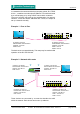
The installation of the module does not require to open the device.
The module is inserted at the front side of the device.
ESD (Electrostatic Discharge)
The components of the module may be damaged by electrostatic
discharge. Observe the precautions (e.g. the use of an antistatic
wrist strap) for the handling of parts that are susceptible to electrical
discharge.
1. Remove all cables from the device.
2. Loose both phillips screws at the left and right side of the blind
plate using the screwdriver.
3. Remove the blind plate or module at the front side of the de-
vice.
As the device must not be operated with an opening, you may want to
keep the blind plate in case of deinstallation of the module.
4. Unpack the module from the protective bag. Touch the module
at the metal plate only.
5. Insert the module with the pins ahead into the guide rails and
put it softly into the device. To connect the pins of the module
with the backplane of the device smart pressure is needed finally.
6. Fix the metal plate of the module screwing both screws in the
front panel.