
Installation guide


DirectOut Technologies
®
page 15 of 30 © 2012 DirectOut GmbH D.O.TEC
®
M.1k2 Hardware & Installation Guide - Version 1.1
CHAPTER 4: Operation
CHAPTER 4: Operation
Introduction
This chapter describes the basic operation of the device. Note that
throughout this manual, the abbreviation FS refers to sample rate or
sample frequency. So, when dealing with scaling factors, the follow-
ing sample rates can be written as:
• 44.1 kHz = 1 FS; 88.2 kHz = 2 FS ; 176 kHz = 4 FS
or
• 48 kHz = 1 FS; 96 kHz = 2 FS; 192 kHz = 4 FS
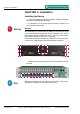
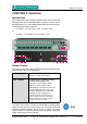
Global Control
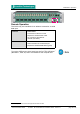
The control on the right of the front panel indicates the power supply.
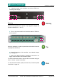
Power switches are on the back panel:
Power 2 Switches
Enable / disable power supply.
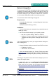
PSU 1 & PSU 2 2 LEDs (green): indicate the status
of both power supply units
LED OFF = Power supply inactive
LED ON = Power supply active
LED blinking 4 times per second = The
power supply was active, and is now
inactive. Whether this is a fault state
depends on the circumstances.
If both PSU LEDs are blinking and the
fan is blowing at full speed, the FPGA is
being programmed. This only happens
during reboot after an update.
The green LEDs (PSU 1 & PSU 2) indicate that a working power
supply is connected to the power supply unit. Note that an unlit LED
does not guarantee that the device is free of voltage. To ensure
that the device is completely disconnected from mains voltage, the
power chords must be disconnected.