
Manual
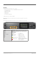
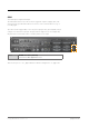
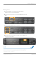
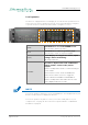
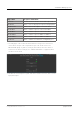
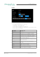
Table Of Contents
- About This Manual
- CHAPTER 1: Overview
- CHAPTER 2: Legal issues & facts
- CHAPTER 3: Installation
- CHAPTER 4: Operation
- CHAPTER 5: Managing Device
- CHAPTER 6: RAV.IO
- Introduction
- Connecting Audio Network
- Status - Overview
- Status - Sync
- Status - Network
- Status - Device
- Status - Input Streams
- Status - Output Streams
- Advanced - Overview
- Advanced - PTP Settings
- Advanced - PTP Unicast
- Advanced - PTP Profile Customized Settings
- Advanced - Current PTP Master
- Advanced - PTP Statistic
- Advanced - PTP Clock Setting
- Advanced - Network Advanced Settings
- Advanced - PTP Jitter
- NMOS - Overview
- NMOS - NIC1 & NIC2
- NMOS - Additional Settings
- Logging
- Statistic
- Switch
- RAV.IO - Firmware Update
- CHAPTER 7: DANTE.IO
- CHAPTER 8: Troubleshooting and Maintenance
- CHAPTER 9: Technical Data
- Index
- Appendix A - DSUB-25 Pin assignment
- Appendix B - DSUB-9 Pin assignment
- Appendix C - Dimensions
- Appendix D - System Update & License Installation

page 53 of 140Prodigy.MP Manual - Version 2.4
GPIO
General Purpose Input and Output
Two MOSFET switches (2 x GPO) can be triggered. A power supply (12 V, max.
200 mA) is also provided. This allows to remote control external devices; e.g. a
recording light.
Two GPIs can be triggered by connecting the input pin with ground (GND) or by a
voltage source between input pin and ground. The high level of the voltage may
range between 2 V and 30 V due to a safety limiter in the input.
GPIO DSUB-9 socket (female)
Connect for GPIO application here.
Observe the pin out - see „Appendix B - DSUB-9 Pin assignment“ on page 135.