
Manual

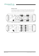


Table Of Contents
- About This Manual
- CHAPTER 1: Overview
- CHAPTER 2: Legal issues & facts
- CHAPTER 3: Installation
- CHAPTER 4: Operation
- CHAPTER 5: Managing Device
- CHAPTER 6: RAV.IO
- Introduction
- Connecting Audio Network
- Status - Overview
- Status - Sync
- Status - Network
- Status - Device
- Status - Input Streams
- Status - Output Streams
- Advanced - Overview
- Advanced - PTP Settings
- Advanced - PTP Unicast
- Advanced - PTP Profile Customized Settings
- Advanced - Current PTP Master
- Advanced - PTP Statistic
- Advanced - PTP Clock Setting
- Advanced - Network Advanced Settings
- Advanced - PTP Jitter
- NMOS - Overview
- NMOS - NIC1 & NIC2
- NMOS - Additional Settings
- Logging
- Statistic
- Switch
- RAV.IO - Firmware Update
- CHAPTER 7: DANTE.IO
- CHAPTER 8: Troubleshooting and Maintenance
- CHAPTER 9: Technical Data
- Index
- Appendix A - DSUB-25 Pin assignment
- Appendix B - DSUB-9 Pin assignment
- Appendix C - Dimensions
- Appendix D - System Update & License Installation

page 42 of 140 Prodigy.MC Manual - Version 2.4
Reference Level
The analog reference level of line inputs and outputs can be adjusted via jumper -
for each channel individually. Check the label on the particular board. At modules
with two boards the input is at the bottom and the pins are accessed from the
side, where as the output is at the top and the pins are accessed from the top.
AN8.I - access from sideways
AN8.O - access from top
CH1CH2CH3CH4
CH8CH7CH6CH5
24/18/15
24/18/15
dBu
AN8.I
CH1
CH2
CH3
CH4
CH8
CH7
CH6
CH5
24/18/15
24/18/15
dBu
AN8.O