PRODIGY.MC User’s Manual Version 2.
Copyright All rights reserved. Permission to reprint or electronically reproduce any document or graphic in whole or in part for any reason is expressly prohibited, unless prior written consent is obtained from the DirectOut GmbH. All trademarks and registered trademarks belong to their respective owners. It cannot be guaranteed that all product names, products, trademarks, requisitions, regulations, guidelines, specifications and norms are free from trade mark rights of third parties.
Table of contents About This Manual 7 How to Use This Manual................................................................................ 7 Conventions................................................................................................... 7 CHAPTER 1: Overview 8 Introduction.................................................................................................... 8 Feature Summary...........................................................................................
CHAPTER 5: Managing Device 54 Introduction.................................................................................................. 54 Getting started............................................................................................. 55 Local operation............................................................................................. 56 MAIN MENU................................................................................................ 57 HOME............................
CHAPTER 7: DANTE.IO 116 Introduction.................................................................................................116 Dante Controller..........................................................................................116 Switch - Configuration................................................................................ 121 DANTE.IO - Firmware Update....................................................................
This page is left blank intentionally. page 6 of 140 Prodigy.MC Manual - Version 2.
About This Manual About This Manual How to Use This Manual This manual guides you through the installation and operation of the device. Use the Table of Contents at the beginning of the manual or Index Directory at the end of the document to locate help on a particular topic. You can access more information and latest news by visiting on the DirectOut website at www.directout.eu. Conventions The following symbols are used to draw your attention to: TI P S indicate useful hints and shortcuts.
CHAPTER 1: Overview CHAPTER 1: Overview Introduction Welcome to PRODIGY.MC, DirectOut’s modular audio converter supporting multiple formats, offering flexible I/O, networked audio, and extremely powerful hardware and software. PRODIGY.MC has been designed to address numerous applications in pro audio, broadcast, installation and studio applications, using a single hardware frame. page 8 of 140 Prodigy.MC Manual - Version 2.
CHAPTER 1: Overview Feature Summary Audio Network Modules * 1 slot (1 x SFP, 2 x RJ45 Socket) - configure to order: - Dante (64 channels) - RAVENNA (128 channels) - SoundGrid (128 channels) MADI Modules * 2 slots - SFP (empty cage without module) - SC-Socket multi/single-mode - coaxial BNC, 75 Ω Converter Modules* 8 slots - individually configurable - 8 channels each: - Analog I/O - Line In / Out - Mic I/O - Mic In / Line Out - Digital I/O - AES3 In / Out Headphones 1 x 6.3 mm jack 1 x 3.
CHAPTER 1: Overview How it works All modules inserted into the mainframe offer a variety of inputs and outputs that are managed by an internal routing matrix. There are eight converter slots equipped with eight channels per module and interface direction for conversion of up to 64 audio channels. Combined with the audio network, two MADI options and the headphones outputs the maximum channel capacity of the device increases to 320 inputs and 324 outputs. Applications PRODIGY.
CHAPTER 1: Overview This page is left blank intentionally. Prodigy.MC Manual - Version 2.
CHAPTER 2: Legal issues & facts CHAPTER 2: Legal issues & facts Before Installing This Device WAR NING! Please read and observe all of the following notes before installing this product: • Check the hardware device for transport damage. • Any devices showing signs of mechanical damage or damage from the spillage of liquids must not be connected to the mains supply, or disconnected from the mains immediately by pulling out the power lead. • All devices must be grounded.
CHAPTER 2: Legal issues & facts First Aid (in case of electric shock) WA R N I N G ! • Do not touch the person or his/her clothing before power is turned off, otherwise you risk sustaining an electric shock yourself. • Separate the person as quickly as possible from the electric power source as follows: - Switch off the equipment. - Unplug or disconnect the mains cable. • Move the person away from the power source by using dry insulating material (such as wood or plastic).
CHAPTER 2: Legal issues & facts Updates DirectOut products are continually in development, and therefore the information in this manual may be superseded by new releases. To access the latest documentation, please visit the DirectOut website: www.directout.eu. This guide refers to System Build 26. Intended Operation PRODIGY.MC is designed for conversion / routing between analog, digital and audio network signals.
CHAPTER 2: Legal issues & facts Conformity & Certificates CE This device complies with the basic requests of applicable EU guidelines. The appropriate procedure for approval has been carried out. RoHS (Restriction of the use of certain Hazardous Substances) This device was constructed fulfilling the directive on the restriction of the use of certain hazardous substances in electrical and electronic equipment 2011/65/EU and 2015/863.
CHAPTER 2: Legal issues & facts Contents The contents of your PRODIGY.MC package should include: • 1 x PRODIGY.MC (19’’, 2 RU) • 2 x power chord with self locking mechanism • 1 x Instruction Leaflet The device provides slots for audio network modules, MADI modules and converter modules. The modules may be delivered separately and require installation first to complete the delivery. TIP Keep any packaging in order to protect the device should it need to be dispatched for service.
CHAPTER 2: Legal issues & facts Accessories BREAKOUT The BREAKOUT series is a range of adaptor boxes available in different variants to extend the coverage of the ANDIAMO and PRODIDGY series. They are equipped with XLR or BNC connectors on the front panel and DSUB-25 connectors on the rear panel. Audio signals are carried passively between the front and rear panels. The small form factor and angle brackets also allow for mounting the devices on the back of an ANDIAMO or PRODIGY unit. BREAKOUT.
CHAPTER 2: Legal issues & facts BREAKOUT.AES - digital input / output, 8 AES3 ports (16 channels) Article Code: DOBOB0887 BREAKOUT.AESID - digital input / output, 16 AESid ports (32 channels) Article Code: DOBOB0888 Patch Chords Cabling from Cordial provides appropriate connection of the BREAKOUT with your device to ensure proper transmission of the audio signals. page 18 of 140 Name Description Article code DSUB25.AN50 Analog patch cable for connection with BREAKOUT.
CHAPTER 2: Legal issues & facts SFP Transceiver - MADI Two different optical SFP transceiver for MADI transmission are available from DirectOut GmbH: • Multimode SFP transceiver with LC connectors (No: DOICT0129) • Singlemode SFP transceiver with LC connectors (No: DOICT0130) Specification of the optical SFP modules: SFP Multimode Singlemode Wavelength TX 1310 nm 1310 nm Wavelenght RX 1310 nm 1310 nm Distance 2 km 10 km Powerbudget (dB) 11 dB 12 dB Protocols Fast Ethernet OC3/STM1 Gigabit
CHAPTER 2: Legal issues & facts SFP Transceiver - Network Two different optical SFP transceiver for 1Gbit/s ethernet transmission are available from DirectOut GmbH: • SFP Copper Transceiver, RJ-45 (No: DOICT0132) • SFP Optical Transceiver, optical LC Single Mode (No: DOICT0133) Specification page 20 of 140 SFP Copper - RJ45 Optical - LC single mode Distance 100 m via CATe cable 2000 m Wavelength - 1310 nm Datarate 12 Mbit/s to 1.25 Gbit/s 2.67 GBit/s Prodigy.MC Manual - Version 2.
CHAPTER 2: Legal issues & facts This page is left blank intentionally. Prodigy.MC Manual - Version 2.
CHAPTER 3: Installation CHAPTER 3: Installation Installing the Device 1. Open the packaging and check that the contents have been delivered complete and undamaged. 2. Fix the device in a 19’’ frame with four screws, or place it on a non-slip horizontal surface. WAR NING! Avoid damage from condensation by waiting for the device to adapt to the environmental temperature. Proper operation can only be guaranteed between temperatures of 5º C and 45º C and a maximum relative humidity of 80%, noncondensing.
CHAPTER 3: Installation 4. Connect the signal cables with the installed modules. For more details about connecting audio network, MADI, AES3 and analog signals see„Slots - Connecting Audio“ on page 31. 5. Connect a network cable to the RJ45-socket MGMT to control the device via network. 6. Using the power cord provided connect the PSUs to a matching power supply. The delivered power cords provide a self-locking mechanism to prevent an accidental disconnect.
CHAPTER 3: Installation 7. Turn on the power switches: Check the display on the front panel for warnings. 8. Enter http:// (default IP: DHCP) in the navigation bar of your browser to open the control website. The IP address is assigned by the DHCP server of your network and can be checked or altered on the display at the front panel. 9. Install globcon on your computer To access all functions the use of globcon is required - see page 16. 10.
CHAPTER 3: Installation Confirm your selection with ‘OK’ The device is displayed in the overview of globcon Double-Click the tiny display of the device to open the control. More information and video tutorials about globcon are available at www.globcon.pro. N OT E For globcon control of the PRODIGY the network infastructure is required to have ports 5002, 5003 and 5004 unfiltered for TCP traffic.
CHAPTER 4: Operation CHAPTER 4: Operation Introduction This chapter describes the basic operation of the device. Note that throughout this manual, the abbreviation FS refers to sample rate or sample frequency. So, when dealing with scaling factors, the following sample rates can be written as: • 44.1 kHz or 48 kHz = 1 FS • 88.2 kHz or 96 kHz = 2 FS • 176.4 kHz or 192 kHz = 4 FS page 26 of 140 Prodigy.MC Manual - Version 2.
CHAPTER 4: Operation Global Control The display on the front panel indicates the power supply. The power switches are on the back panel: PSU 1 & PSU 2 2 Switches Enable / disable power supply. PSU 1 & PSU 2 2 C13 sockets Connect the power supply here (84 - 264 V AC). WA R N I N G Before switching off the power supply, the system must be shut down first - see “Shutdown” on page 67.
CHAPTER 4: Operation Managing Device The device is equipped with a touch-display, an encoder and two push buttons for local control. For remote operation a network socket is provided at the rear panel to operate the device via a browser based GUI or via globcon control. HOME Push-button to access the HOME screen. Press shortly to call the top menu. BACK Push-button to return to previous page. Press shortly to return to the previous page.
CHAPTER 4: Operation Networking PRODIGY.MC uses separate network links for managing the device and networkaudio transmission. LEDs on the front panel indicate the state of both network links. 2 1 MGMT 1 RJ 45 socket Connect here for network control and firmware updates. MGMT LED orange - indicates the link state of the network connection. (ON) = device link active (OFF) = device link not active MGMT LED green - indicates the activity state of the network connection.
CHAPTER 4: Operation NETWORK MGMT LED - indicates the state of the controller for management. (OFF) = controller not available (ON, green) = controller ready (ON, blue) = controller shut down, device is ready to be switched off** NETWORK AUDIO LED - indicates the state of the network audio module. (OFF) = network module not ready (ON) = network module ready (blinking, red) = network module in panic mode* * please contact support@directout.
CHAPTER 4: Operation Slots - Connecting Audio PRODIGY.MC offers three different slot-types that can be assembled individually according the particular requirements.
Slots - Audio Network Modules One audio network slot offers the choice between three audio network protocols. Each module is equipped with 1 x SFP and 2 x RJ45-sockets (Gigabit-Ethernet). Module Protocol Capacity SRC* DANTE.IO Dante / AES67 64 ch in / out no SRC DANTE.SRC.IO Dante / AES67 64 ch in / out yes SRC RAV.IO RAVENNA / AES67 / SMPTE ST 2110-30 / -31 128 ch in / out no SRC RAV.SRC.IO RAVENNA / AES67 / SMPTE ST 2110-30 / -31 128 ch in / out yes SRC SG.
DANTE.IO DANTE.SRC.IO RAV.IO RAV.SRC.IO SG.IO SG.SRC.IO Prodigy.MC Manual - Version 2.
DANTE.IO / DANTE.SRC.IO Three network ports are available for transmission of audio signals (Dante / AES67). The built-in network switch can be operated in three modes: • Switched (all ports in the same network) • Redundant (1 = Primary, 2 = Secondary, 3 = Primary) • Red_Sec (1 = Primary, 2 & 3 = Secondary) The switch will be configured automatically by selecting the respective operation mode in Dante Controller. PRI (1) RJ45 socket (1 Gbit/s) Network interface - connect here for network transmission.
RAV.IO / RAV.SRC.IO Three network ports are available for transmission of audio signals (RAVENNA / AES 67 / SMPTE 2110-30 / -31). The module supports Seamless Protection Switching according to SMPTE 2022-7. PORT 1 PORT 2 RJ45 socket (1 Gbit/s) Network interface - connect here for network transmission. PORT 1 PORT 2 LED orange - indicates the link state of the network connection.
SG.IO / SG.SRC.IO Three network ports are available for transmission of audio signals (SoundGrid). PORT 1 PORT 2 RJ45 socket (1 Gbit/s) Network interface - connect here for network transmission. PORT 1 PORT 2 LED orange - indicates the link state of the network connection. (ON) = device link active (OFF) = device link not active PORT 1 PORT 2 LED green - indicates the activity state of the network connection.
Slots - MADI Modules Two MADI slots offer the choice between three connection standards for transmission of 64 channels @ 1 FS. Module Connection BNC.IO coaxial BNC input / output 75 Ω SFP.IO SFP cage * SC.IO SC-socket duplex multi-mode ** BNC.IO SC.IO SFP.IO * matching SFP transceiver are available from DirectOut - see page 19. ** The SC ports are multi-mode as default, single-mode SC ports are available on request. The housing of single-mode ports is colored blue. multi-mode Prodigy.
BNC.IO OUT IN 2 x BNC socket (coaxial)* OUT: MADI output, connect for MADI output signal here. IN: MADI input, connect MADI input signal here BNC * The labelling of the MADI ports is printed on the Mainframe. SC.IO OUT SC IN 2 x SC socket (optical)* OUT: MADI output, connect for MADI output signal here. IN: MADI input, connect MADI input signal here * The labelling of the MADI ports is printed on the Mainframe. SFP.
Slots - Converter Modules The converter slots can be equipped with analog or digital modules. The pin-out of the DSUB-25 sockets is according to AES59 (‘Tascam’). Analog Modules Module Input AN8.O Output 8 ch line out AN8.IO 8 ch line in 8 ch line out AN8.I 8 ch line in MIC8.HD.I 8 ch mic input (HD) MIC8.HD.IO 8 ch mic input (HD) 8 ch line out MIC8.LINE.IO 8 ch mic input 8 ch line out MIC8.LINE.I 8 ch mic input AN8.O AN8.IO Prodigy.MC Manual - Version 2.
AN8.I MIC8.HD.I MIC8.HD.IO page 40 of 140 Prodigy.MC Manual - Version 2.
MIC8.LINE.IO MIC8.LINE.I Prodigy.MC Manual - Version 2.
Reference Level The analog reference level of line inputs and outputs can be adjusted via jumper for each channel individually. Check the label on the particular board. At modules with two boards the input is at the bottom and the pins are accessed from the side, where as the output is at the top and the pins are accessed from the top. CH7 CH8 CH5 CH6 CH4 CH3 CH2 CH1 AN8.I dBu 24/18/15 24/18/15 CH7 CH3 CH1 CH5 CH4 AN8.O CH2 CH6 CH8 AN8.I - access from sideways dBu 24/18/15 24/18/15 AN8.
Level Settings 15 dBu OK 18 dBu NO! 24 dBu NO! WA R N I N G To prevent damage from the board only set the jumpers parallel in horizontal direction - as illustrated above. N OT E The pinout of the digital and analog I/O is different. Check for appropriate cabling to ensure proper operation and to avoid damages caused by improper connections. The analog outputs are fed by the D/A converters and not a split-out of the analog inputs. WA R N I N G Do not connect voltage sources to the analog outputs.
AN8.O LINE OUTPUT DSUB-25 Port (analog pinout) Analog audio output (balanced) connect for line level audio here AN8.IO LINE OUTPUT DSUB-25 Port (analog pinout) Analog audio output (balanced) connect for line level audio here LINE INPUT DSUB-25 Port (analog pinout) Analog audio input (balanced) connect line level audio source here The pinout complies with AES59 (‘TASCAM pinout’) - see „Appendix A - DSUB-25 Pin assignment“ on page 134. page 44 of 140 Prodigy.MC Manual - Version 2.
AN8.I LINE INPUT DSUB-25 Port (analog pinout) Analog audio input (balanced) connect line level audio source here MIC8.HD.I MIC / LINE INPUT DSUB-25 Port (analog pinout) Analog audio input (balanced) connect mic / line level audio source here The pinout complies with AES59 (‘TASCAM pinout’) - see „Appendix A - DSUB-25 Pin assignment“ on page 134. Prodigy.MC Manual - Version 2.
MIC8.HD.IO LINE OUTPUT DSUB-25 Port (analog pinout) Analog audio output (balanced) connect for line level audio here MIC / LINE INPUT DSUB-25 Port (analog pinout) Analog audio input (balanced) connect mic / line level audio source here MIC8.LINE.
MIC8.LINE.I MIC / LINE INPUT DSUB-25 Port (analog pinout) Analog audio input (balanced) connect mic / line level audio source here The pinout complies with AES59 (‘TASCAM pinout’) - see „Appendix A - DSUB-25 Pin assignment“ on page 134. Prodigy.MC Manual - Version 2.
Digital Modules Module Input Output AES4.IO 4 port AES3 in 4 port AES3 out AES4.SRC.IO 4 port AES3 in with SRC 4 port AES3 out AES4.IO AES4.SRC.IO NOT E An AES4.IO transports eight audio channels - two audio channels per port. page 48 of 140 Prodigy.MC Manual - Version 2.
AES4.IO AES3 INPUT / OUTPUT DSUB-25 Port (digital pinout) Digital audio input and output (AES3) connect for digital audio here AES4.SRC.IO AES3 INPUT (SRC) / OUTPUT DSUB-25 Port (digital pinout) Digital audio input and output (AES3) connect for digital audio here. Input offers switchable Sample Rate Conversion. The pinout complies with AES59 (‘TASCAM pinout’) - see „Appendix A - DSUB-25 Pin assignment“ on page 134. Prodigy.MC Manual - Version 2.
Word clock The word clock output provides the system clock that is either derived from PTP / Network Audio input, AES input, word clock input, MADI input or internal clock generator. WCK OUT BNC socket (coaxial), 75 Ω System clock output - connect for word clock output signal here. WCK IN BNC socket (coaxial), 75 Ω Connect word clock or AES3 DARS (Digital Audio Reference Signal) here. The word clock input also accepts a AES3 frame (AES11).
Clocking The device offers several options for clocking. • PTP (Precision Time Protocol) - IEEE1588-2008 / PTPv 1 & 2 * • SoundGrid (SoE) * • Word Clock • MADI input * • AES3 input * • internal clock generator * depending on the modules installed. When PTP (network) is selected the device can either act as slave or as network grandmaster. The front panel informs about selected clock sources and their lock / sync state.
USB The USB port at the rear panel is used for legacy control of ANDIAMO devices via globcon bridge. USB USB 2.0 socket (Type B) Connect here for legacy control. GPIO General Purpose Input and Output Two MOSFET switches (2 x GPO) can be triggered. A power supply (12 V, max. 200 mA) is also provided. This allows to remote control external devices; e.g. a recording light. Two GPIs can be triggered by connecting the input pin with ground (GND) or by a voltage source between input pin and ground.
This page is left blank intentionally. Prodigy.MC Manual - Version 2.
CHAPTER 5: Managing Device CHAPTER 5: Managing Device Introduction PRODIGY.MC can be managed via multiple user interfaces: • local touch display on the front panel • browser based control / website • globcon control Further a JSON plug-in (JavaScript Object Notation) is available for management. This documentation explains the management via touch-display and browser control. For the use of globcon control there are video tutorials available that can be found at www.globcon.pro.
CHAPTER 5: Managing Device Getting started 1. Check the hardware - the housing must be closed completely. Empty slots require covering with a blank plate. 2. Check network connection with the MGMT port on the rear panel. 3. Check the power cabling and switch on the device. 4. After a few seconds the boot process of the device is complete. Check the display on the front panel for the IP address. N OT E The device will look for a DHCP server in the network to obtain it’s IP address.
CHAPTER 5: Managing Device Local operation The device is equipped with a touch-display, an encoder and two push buttons for local control. For remote operation a network socket is provided at the rear panel to operate the device via a browser based GUI or via globcon control. HOME Push-button to access the HOME screen. Press shortly to call the top menu. BACK Push-button to return to previous page. Press shortly to return to the previous page.
CHAPTER 5: Managing Device MAIN MENU The MAIN MENU displays: • Icons to access the HOME menu and further settings Tap / click to open Home icon HOME Menu Clock Clock Settings Snapshots Snapshot list for recall Settings Device Settings Network Network Settings for the Management Port Info Display of Device Name, System Build, FPGA Version, cored version, Frontpanel version, License information Download Support Archive Prodigy.MC Manual - Version 2.
CHAPTER 5: Managing Device HOME The HOME screen displays: • Level metering (input / output) of all eight converter slots • Level metering of headphones outputs • Device name (Device) • IP address for device management (Mgmt IP) • Temperature • Clock Master • Sample Rate • LTC Reader display (LTC) Tap / click to open Burger icon Main Menu Clock Master Clock Settings Mgmt IP Network Settings Level Meter zoomed display of eight channels Encoder (CONTROL) Phones volume control or to toggle the sele
CHAPTER 5: Managing Device Tap / click to open / Lock icon Lock or unlock the device control with a pin code. * * A four-digit pin code needs to be defined when locking for the first time. To unlock device the pin code is required. The pin code can be reset in the PRODIGY.MC plugin of globcon (Settings / Front Panel) when the device is locked or in the device settings (see “DEVICE SETTINGS” on page 67) when the device is unlocked. Prodigy.MC Manual - Version 2.
CHAPTER 5: Managing Device CLOCK The CLOCK Settings displays: • Clock Master: Current master for system clock • Sample Rate: measured sample rate • Icons to adjust the scaling factor of the base rate • Icons to select Clock Mode (Auto or Manual) and to open FastSRC™ settings • Icons to select the clock master page 60 of 140 Tap / click to open / set* Burger icon Main Menu 1 FS Scaling factor to 1 FS (usually 44.1 or 48 kHz) 2 FS Scaling factor to 2 FS (usually 88.
CHAPTER 5: Managing Device WCK Word Clock input as Clock Master NET Audio Network as Clock Master SLOT AES3 input as Clock Master *** INT Internal Generator as Clock Master 44.1 Base Rate to 44.1 kHz [INT] 48 Base Rate to 48 kHz [INT] * the value set is marked by the particular icon with a blue background ** The priority setting allows to define several fallbacks if a clock source fails.
CHAPTER 5: Managing Device FastSRC™ The ‘FastSRC™’ is a low latency sample rate converter that is available for the MADI I/Os and the audio network I/O.
CHAPTER 5: Managing Device MADI FSRC IN NET FSRC FSRC Routing MADI OUT FSRC NET About FastSRC™ DirectOut’s FastSRC™ (FSRC) is a low latency sample rate converter for when two digital interfaces of a device must work in different clock domains. FastSRC™ combines good sound quality with very low latency of less than 0.15 msecs and is invaluable in live sound applications and a “life-saver” in critical situations.
CHAPTER 5: Managing Device SNAPSHOTS The SNAPSHOT screen displays: • list of snapshots that are stored in the device (up to 99 snapshots) Tap / click to recall snapshot entry snapshot - after confirming a prompt Each snapshot which is created in globcon will be stored into the device. As a snapshot can be stored within a globcon project, it is possible to reconfigure a device including snapshots via ‘Push’ function from globcon. The selected snapshot is surrounded by a red frame.
CHAPTER 5: Managing Device Snapshots - Compliance compliant Snapshot Data Set matches the Configuration Settings of the device. non-compliant Snapshot Data Set does not match the Configuration Settings of the device. Conform procedure required for recall in Show Mode or recall with full Scope Set in Configuration Mode, thus changing the Configuration Settings. See document ‘Info PRODIGY.MC Supplemental’ for more information about the Operating Modes and Snapshots. Prodigy.MC Manual - Version 2.
CHAPTER 5: Managing Device NETWORK SETTINGS The NETWORK Settings displays: • IP Address for the management port (MGMT) • Subnet Mask for the management port (MGMT) • Gateway for the management port (MGMT) Tap / click Function Burger icon Link to Main Menu DHCP Enable / Disable DHCP * grey = DHCP OFF, manual input required blue = DHCP ON, network settings are assigned automatically SAVE Stores changes to the device Input field Input of values ** * DHCP (Dynamic Host Control Protocol) = device
CHAPTER 5: Managing Device DEVICE SETTINGS Enable Reboot/Shutdown from remote: The DEVICE Settings allows to: • Reset the four-digit PIN code used for device lock • Enable / disable Auto Lock • Define the timeout for Auto Lock function • Reboot the device into update mode for system updates or license installation • Shut down the device to ensure proper file operation before switching the device off. • Manage security setting for shutdown or reboot from remote - see page 68.
CHAPTER 5: Managing Device Shutdown / Reboot into update mode Both commands can also be used remotely via globcon or the web UI, once the feature has been activated on the front panel: Enable Reboot/Shutdown from remote: This setting is persistent and will be restored after a power-cycle or reboot. WAR NING Enabling ‘Reboot/Shutdown from remote’ can be a security risk, if the management network can be accessed freely. It is disabled by default.
CHAPTER 5: Managing Device DEVICE INFO DEVICE INFO displays: • Device Name • System Build: version and date • FPGA Version: audio processing • cored Version: device management • Frontpanel Version: local operation • Support: Support Archive • License information about installed licenses and their service state • License information for open source software that is used by this device Tap / click to open / generate Burger icon Main Menu Download Support Archive * a support archive (*.
CHAPTER 5: Managing Device PRODIGY License Information For enhanced scalability the PRODIGY series can be ordered with different system licenses - Essential, Advanced, Unlimited. Additional single licenses can be acquired on demand.
CHAPTER 5: Managing Device LEVEL METER - INPUT (MIC8.LINE.IO) The LEVEL METER - INPUT (MIC8.LINE.IO) displays: • Level meters for a single converter slot - 8 channels • Slot number and module type inserted • control for input level, mute and phantom power (depending on the module) Tap / click to Arrow left navigate to previous module* Arrow right navigate to next module* INPUT SLOT return to HOME screen Trim** / Gain select field(s) for modifying values of trim and gain.
CHAPTER 5: Managing Device LEVEL METER - INPUT (AN8.IO) The LEVEL METER - INPUT displays: • Level meters for a single converter slot - 8 channels • Slot number and module type inserted Tap / click to Arrow left navigate to previous module* Arrow right navigate to next module* INPUT SLOT return to HOME screen * the arrows are used for circular navigation through slots 1 to 8 input, followed by slot 1 to 8 output. page 72 of 140 Prodigy.MC Manual - Version 2.
CHAPTER 5: Managing Device LEVEL METER - OUTPUT The LEVEL METER - OUTPUT displays: • Level meters for a single converter slot - 8 channels • Slot number and module type inserted • control for level, mute and phantom power (depending on the module) Tap / click to Arrow left navigate to previous module* Arrow right navigate to next module* OUTPUT SLOT return to HOME screen Trim** / Gain select field(s) for modifying values of trim and gain.
CHAPTER 6: RAV.IO CHAPTER 6: RAV.IO Introduction RAV.IO is an audio network module for RAVENNA / AES67. All functions of the device are accessible through a browser based interface (hmtl5 / javascript). The size of the window and the zoom level can be varied. The page is organized in tabs, pulldown menus or hyperlinks offer access to the values of a parameter. Some values use an input field (e.g. IP address). page 74 of 140 Prodigy.MC Manual - Version 2.
CHAPTER 6: RAV.IO Connecting Audio Network To access the control page: • connect the network with one port • enter http:// (default IP @ PORT 1: 192.168.0.1) in the navigation bar of your browser The three physical network ports (Port 1 to 3) are managed by two independent internal network interfaces (NIC 1 / NIC 2). Port 1 is fixed assigned to NIC 1. Port 2 and 3 can be assigned to either NIC 1 or NIC 2 on the SWITCH tab see p 111.
CHAPTER 6: RAV.IO Status - Sync PTP, Ext Displays clock source and state for the main frame: (OFF) = not locked (ON) = locked and in sync with clock master (blinking) = locked but not in sync with clock master Clock master Pulldown menu to select clock source of the main frame (PTP, extern) Sample rate Pulldown menu to adjust sample rate of the main frame (44.1 / 48 / 88.2 / 96 / 176.4 / 192 kHz). PTP state State of PTP (Master / Slave).
CHAPTER 6: RAV.IO PTP Settings PTP Input NIC selection for PTP clock input. ‘NIC 1 & 2’ means input redundancy. IP Mode PTP via multicast, unicast or in hybrid mode. * Mode PTP-clock master / slave configuration is auto negotiated between devices in the network. Module’s master / slave state may change automatically. Profile PTP profile selection (default E2E, default P2P, media E2E, media P2P, customized) Customized profile Edit opens the tab ‘ADVANCED’ to adjust the custom profile.
CHAPTER 6: RAV.IO Status - Network Name Module’s name in the network. Used e.g. for mDNS service. The name needs to be unique throughout the network. NIC 1 / NIC 2 Monitoring state of network interface controller (OFF) = not connected (ON) = connected with the network MAC address Hardware identification of network interface controller.
CHAPTER 6: RAV.IO Network Settings The two network interface controllers (NIC 1 / NIC 2) are configured individually. Device name Input field - Module’s name in the network. Used e.g. for mDNS service. The name needs to be unique throughout the network. Dynamic IP address (IPv4) Switch to enable the device’s DHCP client. IP address is assigned by DHCP server. If no DHCP is available the IP address is determined via Zeroconf. Static IP address (IPv4) Switch to disable the device’s DHCP client.
CHAPTER 6: RAV.IO Status - Device Settings Opens a popup window to configure the device. Load preset Opens a dialog to store the device settings to a file. Filetype: .rps Save preset Opens a dialog to restore the device settings from a file. Filetype: .rps Hyperlinks: • Settings (p 80) • Load preset (p 81) • Save preset Settings page 80 of 140 AoIP Module SW Module´s software version. It is updated together with hardware version via network. AoIP Module HW Module´s bitstream version.
CHAPTER 6: RAV.IO Load Preset The device configuration can be stored to a single file (.rps). Restoring the configuration a dialog prompts for selection of individual settings. This enhances flexibility at setup changes when a particular adjustment shall be preserved or just a single adjustment shall be restored. Prodigy.MC Manual - Version 2.
CHAPTER 6: RAV.IO Status - Input Streams The module can subscribe up to 32 streams. The overview displays the basic information of each stream. The input stream name can be set manually (discovery protocol: manually, see page p 90) overriding the SDP’s stream name information. A backup stream can be defined as source after an adjustable timeout. A central active / inactive switch allows to toggle the stream state of all input streams at once.
CHAPTER 6: RAV.IO 01 to 32 Click to activate or deactivate single stream. = stream activated = stream deactivated = stream not active, defined as backup-stream INPUT STREAMS Click to activate or deactivate all streams. = activate all streams = deactivate all streams (requires confirmation) Prodigy.MC Manual - Version 2.
CHAPTER 6: RAV.IO Backup Streams Example: Backup stream (input 3) that will act as source in the audio matrix if the current session (input 1) fails. Switch-over occurs after the defined timeout (1s). Stream 3 is marked accordingly in the status view Input 1 failed and Input 3 becomes active after the timeout. NOT E In case the main input fails the main stream is stopped (IGMP LEAVE) before the backup stream is being activated.
CHAPTER 6: RAV.IO Hyperlinks: • Name (p 86) Mouse over: • LED - indicating stream state N OT E Source-Specific Multicast (SSM) support for IGMP v3, v2 and v1 (SSM via protocol only in IGMP v3, SSM via internal filtering is applied for IGMP v2 and v1) see “Source Specific Multicast” on page 90. Prodigy.MC Manual - Version 2.
CHAPTER 6: RAV.IO Input Stream Settings Up to 32 input streams can be subscribed. Each stream is organized in a ‘RAVENNA session’ (SDP = Session Description Protocol) that describes the stream parameters (audio channels, audio format, etc.). The stream settings allow to adjust the processing of the received audio data (offset, signal routing). The receiving of stream data starts once the stream has been enabled. The settings displayed vary depending on the selected discovery protocol.
CHAPTER 6: RAV.IO Activate stream Stores parameters and activates or deactivates the receiving of audio data. (Unicast: additionally the negotiation of the connection) Stream input Selects one or both NICs used for stream input. Both NICs means input redundancy. Backup Stream Selects a backup stream that will act as source in the audio matrix if the current session fails. Switch-over occurs after the defined timeout.
CHAPTER 6: RAV.IO Stream Discovery in AoIP environments is a colorful mixture of different mechanisms. To serve a successful stream management RAV.IO provides a bunch of options, not making operation easier but effective. Discovery RTSP (Session) Discovery RTSP (URL) URL URL (Uniform Ressource Locator) of the session of the device that is serving streams. Examples: rtsp://192.168.74.44/by-id/1 or rtsp://PRODIGY-RAV-IO.
CHAPTER 6: RAV.IO Discovery SAP SAP is used in Dante environments. Discovery NMOS Session [MAC Address of sender] stream name @NIC Refresh Initiates a scan for available streams. NMOS is suited for use in SMPTE ST 2110 environments. Prodigy.MC Manual - Version 2.
CHAPTER 6: RAV.IO Manual Setup Stream name (manual) Stream name for display in status view and matrix. Can be specified individually, different than the name gathered from the SDP. Number of channels Number of audio channels in the stream RTP-Payload-ID RTP-Payload-ID of the audio stream (Real-Time Transport Protocol). Describes the format of the transported content.
CHAPTER 6: RAV.IO This page is left blank intentionally. Prodigy.MC Manual - Version 2.
CHAPTER 6: RAV.IO Status - Output Streams The device can send up to 32 streams. The overview displays the basic information of each stream. 01 to 32 State of outgoing streams (OFF) = stream not activated (ON) = stream activated, sending data (ON) = stream activated, stream output via both NICs selected, but one NIC is not linked to the network.
CHAPTER 6: RAV.IO TI P AES67 Streams To create output streams for interoperability in AES67 environments please consult the information document Info - AES67 Streams. TI P SMPTE 2110-30 / -31 Streams To create output streams for interoperability in SMPTE ST 2110 environments please consult the information document Info - ST2110-30 Streams. Both documents are available at http://academy.directout.eu. Prodigy.MC Manual - Version 2.
CHAPTER 6: RAV.IO Output Stream Settings Up to 32 output streams can be sent to the network. Each stream is organized in a session (SDP = Session Description Protocol) that describes the stream parameters (audio channels, audio format, etc.). Each stream may be labelled with an individual stream name (ASCII) which is useful for enhanced comfort at organizing the setup. The stream settings allow to adjust the processing of the sent audio data (blocks per frame, format, signal routing, ...).
CHAPTER 6: RAV.IO * Activate stream Stores parameters and activates or deactivates the receiving of audio data. (Unicast: additionally the negotiation of the connection) Stream Output Selects one or both NICs used for stream output. Both NICs means output redundancy. Stream name (ASCII) Individually defined name of an output stream. It is used in the URL which is indicated in different ways below.
CHAPTER 6: RAV.
CHAPTER 6: RAV.IO Advanced - PTP Settings * PTP Input Selects one or both network ports used for PTP input. Both ports means input redundancy. * IP Mode Multicast = Hybrid = Unicast = Sync messages and delay request are sent as multicast message to every node within the network. Sync messages are sent as multicast, delay requests are sent as unicast messages directly to the Grandmaster or Boundary Clock.
CHAPTER 6: RAV.IO * Mode auto = slave only = preferred master = master only = PTP-clock master / slave configuration is auto negotiated between devices in the network. Module’s master / slave state may change automatically. PTP-clock slave configuration is preferred. Module clocks to another device in the network PTP-clock master configuration is preferred. Module acts as network grandmaster. Priority values are adjusted automatically to ensure Grandmaster status.
CHAPTER 6: RAV.IO Advanced - PTP Unicast * Auto Detect GM on = enables the automatic detection of the grandmaster * off = IP address of grandmaster needs to be defined manually Grant duration (sec) Time period during which the slave receives sync messages from the grandmaster.** Grandmaster IP IP address of the grandmaster. *** ‘Auto Detect GM’ is a proprietary function and might not be supported by 3rd party GMs.
CHAPTER 6: RAV.IO Advanced - PTP Profile Customized Settings The settings become available with PTP profile set to ‘customized’.
CHAPTER 6: RAV.IO One step clock Timestamp of PTP-clock is integrated in PTP-syncpackets. No follow-up packets are sent. No = Two step clock is used Slave only Yes = PTP-clock is always slave. Delay mechanism E2E - Offset slave-to-master is determined by End-ToEnd packets. P2P - Offset master-to-slave and slave-to-master is determined by Peer-To-Peer packets. Advanced - Current PTP Master Monitoring display only.
CHAPTER 6: RAV.IO Advanced - PTP Statistic Monitoring display only.
CHAPTER 6: RAV.IO Advanced - Network Advanced Settings IGMP NIC 1 Definition or auto-select of IGMP version used to connect to a multicast router at NIC 1.
CHAPTER 6: RAV.IO NOT E Source-Specific Multicast (SSM) support for IGMP v3, v2 and v1 (SSM via protocol only in IGMP v3, SSM via internal filtering is applied for IGMP v2 and v1) see “Source Specific Multicast” on page 90. page 104 of 140 Prodigy.MC Manual - Version 2.
CHAPTER 6: RAV.IO Advanced - PTP Jitter Graphical display of measured PTP jitter. N OT E An error message next to Jitter measurement is displayed if delay requests are not being answered by Grandmaster. Prodigy.MC Manual - Version 2.
CHAPTER 6: RAV.IO NMOS - Overview NMOS provides a family of specifications related to networked media for professional applications. It is produced by the Advanced Media Workflow Association (AMWA). Support for NMOS is introduced with the AoIP Module version SW 0.17 / HW 0.46 according to the specifications: • IS-04 Discovery & Registration • IS-05 Device Connection Management IS-04 allows control and monitoring applications to find the resources on a network.
CHAPTER 6: RAV.IO NMOS - NIC1 & NIC2 The port entries for NIC1 and NIC2 are pre-configured by default. Modifications are possible but not necessary. Settings (NIC1 + NIC2) Apply Stores modifications of the port settings. Reboot required. NMOS - Additional Settings Seed id Unique identifier, subordered entities are derived from the seed id. Generate new seed id Generate Generates a new unique identifier. Reboot required.
CHAPTER 6: RAV.IO Logging The tab ‘LOGGING’ displays logging depending on the ‘Log Settings’. The logging can be enabled individually for different protocols, each of with an adjustable filter. An adjustable log level specifies the information detail of each entry. To save a log the content of the view can be copied and pasted to a text document.
CHAPTER 6: RAV.
CHAPTER 6: RAV.IO Statistic The tab ‘STATISTIC’ displays an overview of the CPU load of the particular processes, an error counter and a monitor display to indicate the incoming (RX) and outgoing (TX) network traffic on both network ports individually. See “Protocol Types” on page 109. page 110 of 140 Prodigy.MC Manual - Version 2.
CHAPTER 6: RAV.IO Switch The module features two RJ45 sockets and an SFP cage managed by two independent network interfaces (NIC 1 / NIC 2). • Port 1 is fixed assigned to NIC 1. • Port 2 and 3 can be assigned to either NIC 1 or NIC 2 on the SWITCH tab N OT E If you want to use a port that is not assigned to a NIC e.g. to patch the device‘s management port (MGMT) into the audio network, you can link it to one of the audio ports.
CHAPTER 6: RAV.IO SWITCH - Configurations Port 1 NIC 1 Port 2 NIC 2 NIC 2 RAV.IO NIC 1 RAV.IO Port 3 RAV.IO Audio & Control via Port 1 and Port 2 Port 1 NIC 1 Port 2 NIC 2 NIC 2 RAV.IO NIC 1 RAV.IO Port 3 RAV.IO Audio & Control via Port 1 and Port 3 Port 1 NIC 1 Port 2 NIC 2 Switched to Port 02 NIC 2 RAV.IO NIC 1 RAV.IO Port 3 RAV.IO Audio & Control via Port 1 and Port 2 Extra ethernet traffic via Port 3 (NIC 2) page 112 of 140 Prodigy.MC Manual - Version 2.
CHAPTER 6: RAV.IO Port 1 NIC 1 Port 2 NIC 2 NIC 2 Switched NIC 1 RAV.IO to Port 03 RAV.IO RAV.IO Audio & Control via Port 1 and Port 3 Extra ethernet traffic via Port 2 (NIC 2) Port 3 Port 1 NIC 1 Port 2 NIC 2 NIC 2 RAV.IO Switched to Port 01 NIC 1 RAV.IO Port 3 RAV.IO Audio & Control via Port 1 and Port 3 Extra ethernet traffic via Port 2 (NIC 1)* Port 1 NIC 1 Port 2 NIC 2 Switched to Port 01 NIC 2 RAV.IO NIC 1 RAV.IO Port 3 RAV.
CHAPTER 6: RAV.IO Device Management over the audio network This configuration is exemplary to illustrate the possibility to integrate the management data that is used to control the device into the audio network. MGMT NIC 2 RAV.IO NIC 1 RAV.IO • connect the MGMT port of the device with Port 2 of the RAV.IO • connect the RAVENNA network to Port 1 of the RAV.IO • connect the RAVENNA network to Port 3 of the RAV.IO (if needed) Switch configuration Port 1 RAV.
CHAPTER 6: RAV.IO RAV.IO - Firmware Update The RAV.IO module is updated via network. Visit www.directout.eu and navigate to a PRODIGY product page. Download: • PRODIGY RAV.IO Firmware Open the control page of the module and navigate to the tab STATUS and click SETTINGS in the top right corner (p 80). Click ‘Update’ and browse to the update file after unzipping first. Example: rav_io_hw_0_13_sw_0_16.update Folllow the instructions displayed.
CHAPTER 7: DANTE.IO CHAPTER 7: DANTE.IO Introduction DANTE.IO is an audio network module for Dante / AES67. All functions of the device are managed via the Dante Controller application. To control the functions of the host device connect your computer with the management network port (MGMT) and use the globcon application. Dante Controller To control a Dante network the application 'Dante Controller' needs to run on a computer that is connected to the audio network.
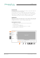
CHAPTER 7: DANTE.IO Network View The 'Network View' is organised in several tabs. All detected Dante devices are shown on a list. The DANTE.IO is delivered with the network interface set to DHCP as a default. Dante Controller can be used to discover the device on the network and change the IP configuration if necessary - see “Network Config” on page 120. Clock Status The tab ‘Clock Status’ informs about the clock settings of each connected device and allows to modify them.
CHAPTER 7: DANTE.IO Routing The audio signal routing is accessible in the tab 'Routing' 'Dante Receivers' in the vertical column displays the receiving devices (= destinations). 'Dante Transmitters' in the horizontal row displays the transmitting devices (= sources). The channel list can be expanded or collapsed for each device. Connections are made by clicking into the matrix.
CHAPTER 7: DANTE.IO Device View The 'Device View' is also organised in to several tabs. It can be opened by double-clicking on to a device name in the 'Network View'. The status tab informs about the current firmware and software versions. TI P See “DANTE.IO - Firmware Update” on page 122. Prodigy.MC Manual - Version 2.
CHAPTER 7: DANTE.IO Network Config The tab 'Network Config' of the device view provides access to the operating mode of the built-in network switch and the network settings of the device. Device Config The tab ‘Device Config’ to adjust the device name, sample rate, encoding modes and more. page 120 of 140 Prodigy.MC Manual - Version 2.
CHAPTER 7: DANTE.IO Switch - Configuration Three network ports are available for transmission of audio signals and remote control. The built-in network switch can be operated in three modes: • Switched (all ports in the same network) • Redundant (1 = Primary, 2 = Secondary, 3 = Primary) • Red_Sec (1 = Primary, 2 & 3 = Secondary) The switch will be configured automatically by selecting the respective operation mode in Dante Controller.
CHAPTER 7: DANTE.IO DANTE.IO - Firmware Update The device can be updated either via the: • online procedure using the ‘Dante Updater’ which is integrated in the latest version of ‘Dante Controller’. • offline procedure using an update file and ‚Dante Firmware Update Manager‘ WAR NING It is strongly recommended to backup the device configuration before running any update. Online Procedure 1. Open Dante Controller 2. Menu: View - Dante Updater (CMD-U) 3.
CHAPTER 7: DANTE.IO 4. Confirm and take your time until the update procedure has finished. 5. Mark the updated device for reboot and click ‘Reboot Selected Devices’. Prodigy.MC Manual - Version 2.
CHAPTER 7: DANTE.IO 6. After Reboot the Updater will report the Update Status. Offline Procedure 1. Download the update file from the product page at www.directout.eu. 2. Open ‚Dante Firmware Update Manager‘ and follow the instructions. https://www.audinate.com/products/firmware-update-manager page 124 of 140 Prodigy.MC Manual - Version 2.
This page is left blank intentionally. Prodigy.MC Manual - Version 2.
CHAPTER 8: Troubleshooting and Maintenance CHAPTER 8: Troubleshooting and Maintenance Troubleshooting To identify a possible defect with the device please consult the following table. If the fault cannot be resolved using these instructions, please contact your local DirectOut representative or visit support.directout.eu. page 126 of 140 Issue Possible reason Solution Device doesn’t work. Power supply is broken.
Maintenance To clean the device, use a soft, dry cloth. To protect the surface, avoid using cleaning agents. N OT E ! The device should be disconnected from the power supply during the cleaning process. Prodigy.MC Manual - Version 2.
CHAPTER 9: Technical Data CHAPTER 9: Technical Data Dimensions (sketch on page 136) • Width 19’’ (483 mm) • Height 2 RU (89 mm) • Depth 10’’ (254 mm) • Weight about 10 kg Power Consumption • 20 W to 110 W, module dependent Power Supply • 2 x 84 V - 264 V AC / 47 Hz - 63 Hz / Safety class 1 Fuses • Fuse 250 V - 4 A (slow-blow) – 2 fuses per power supply Environmental Conditions • Operating temperature +5°C up to +45°C • Relative humidity: 10% - 80%, non condensing Display • 5.
CHAPTER 9: Technical Data Sample Rate • 30 - 50 kHz @ 1 FS • 60 - 100 kHz @ 2 FS • 120 - 200 kHz @ 4 FS Phones Out 1 • 1 x 6.3 mm TRS jack, mono / stereo • Output level: max. +18 dBu • SNR: -115 dB RMS (20 Hz - 20 kHz) / -118 dB(A) • THD+N @ 0 dBFS: -105 dB @ 600 Ω Phones Out 2 • 1 x 3.5 mm TRS jack, mono / stereo • Output level: max.
CHAPTER 9: Technical Data Analog I/O level line • +15 / +18 / +24 dBu changeable via jumper on module MIC8.HD.I • Input sensitivity: -55 dBu to +30 dBu • EIN: -128 dBu • THD @ -1 dBFS: -113 dB • Frequency response: -0.15 dB (10 Hz) / -0.15 dB (20 kHz) • 30 dB PAD (switchable) • +48 V phantom power (switchable) MIC8.LINE.IO • Input sensitivity: -55 dBu to +24 dBu • EIN: -118 dBu • SNR: -115 dBFS (20 Hz - 20 kHz) / -118 dB(A) @ 0dB Gain • THD @ -1 dBFS: -113 dB • Frequency response: -0.
CHAPTER 9: Technical Data MIC8.HD.I • 8 ch mic high definition input, 1 x DSUB-25, balanced MIC8.HD.IO • 8 ch mic high definition input / line output, 2 x DSUB-25, balanced MIC8.LINE.IO • 8 ch mic/line input / line output, 2 x DSUB-25, balanced MIC8.LINE.I 8 ch mic/line input, 1 x DSUB-25, balanced AES4.IO • 4 port AES3 input / output, 1 x DSUB-25 (8 audio channels) AES4.SRC.IO • 4 port AES3 input with SRC / output, 1 x DSUB-25 (8 audio channels) BNC.
Index Index A Accessory BREAKOUT........................................... 17 Patch Chords........................................ 18 SFP Transceiver - MADI......................... 19 SFP Transceiver - Network..................... 20 AES59................................ 44, 45, 46, 47, 49 AES67....................................................... 93 Analog Split............................................... 43 ANDIAMO................................................ 52 G globcon......................
Index R Reboot into update mode......................... 67 Remote Control........................................ 16 Dante Controller.................................. 116 Reset see Factory Reset W Warranty................................................... 14 WEEE See Conformity & Certificates: WEEE Word clock................................................ 50 S Scaling Factor........................................... 26 Session Description Protocol.................... 94 SFP Modules...................
Appendix A - DSUB-25 Pin assignment Appendix A - DSUB-25 Pin assignment The pinout of the DSUB-25 connectors for the transmission of analog and AES3 audio signals follows the AES59 specification.
Appendix B - DSUB-9 Pin assignment Appendix B - DSUB-9 Pin assignment The pinout of the DSUB-9 connector for the GPI (General Purpose Input) and GPO (General Purpose Output) connection. 5 4 9 3 8 2 7 1 6 jack - female PIN Signal 1 GND 2 GND 3 GND 4 + 12 V 5 + 12 V 6 GPI 2 7 GPI 1 8 GPO 2 9 GPO 1 GPI - 3.3 V CMOS compatible, low active Can be triggered by connecting the input pin with ground (GND) or by a voltage source between input pin and ground.
Appendix C - Dimensions Appendix C - Dimensions 484 7,5 88,5 44 10 10 442 255,2 37,5 260 255,2 434 37,5 7,5 31,6 76,2 465,7 19Zoll 2HE, Depht 260mm page 136 of 140 Prodigy.MC Manual - Version 2.
Appendix D - System Update & License Installation Appendix D - System Update & License Installation To update the system of PRODIGY or to install a license the device must be rebooted in Update Mode. WA R N I N G ! It is strongly recommended to backup the device configuration (Save Preset) before running any update. 1. Download Image Archive from the product page at www.directout.eu 2. Unzip the Image file => prodigy__system_update__.pdgy 3.
Appendix D - System Update & License Installation 4. Enter the device’s IP Address in your browser (Mozilla Firefox or Google Chrome). It is displayed in the front panel display. The IP address may vary in update mode when the network settings are set to DHCP. T IP To keep the identical IP address in both operating modes, configure the network settings manually before rebooting into update mode. 5. Click Start Update 6. Choose the downloaded file for upload (*.
Appendix D - System Update & License Installation 7. Once the reboot message appears you can power cycle the unit. TI P Installation of multiple licenses (not a system update!): To install multiple licenses without rebooting the device in between, click on the HOME icon after the installation of a license has been completed successfully. 8. Check the new build version in the SETTINGS DEVICE INFO. Prodigy.MC Manual - Version 2.
DirectOut GmbH Leipziger Strasse 32 09648 Mittweida Germany T: +49-3727-5665-100 F: +49-3727-5665-101 www.directout.