480XP Installation Guide NOTE: This product is intended for installation by a professional installer only! Any attempt to install this product by any person other than a trained professional may result in severe damage to a vehicle’s electrical system and components. © 2002 Directed Electronics, Inc.
The Bitwriter® (p/n 998T) requires chip version 1.4 or newer to program this unit. Bitwriter™, Code Hopping™, DEI®, Doubleguard®, ESP™, FailSafe®, Ghost Switch™, Learn Routine™, Nite-Lite®, Nuisance Prevention® Circuitry, NPC®, Revenger®, Silent Mode™, Soft Chirp®, Stinger®, Valet®, Vehicle Recovery System®, VRS®, and Warn Away® are all Trademarks or Registered Trademarks of Directed Electronics, Inc. www.directechs.
Table of Contents Warning! Safety First ................................4 Installation Points to Remember ...............5 Before Beginning the Installation ..........5 Finding the Tachometer Wire ...............5 Finding the WAIT-TO-START Bulb Wire for Diesels ....................................6 After the Installation .............................6 Vehicle Anti-Theft Systems (Immobilizers) ......................................6 Primary Harness (H1) Wire Connection Guide ...........................
Warning! Safety First Due to the complexity of this system, installation of this product must only be performed by an authorized Directed dealer. ➤ When properly installed, this system can start the vehicle via a command signal from the remote control transmitter. Therefore, never operate the system in an area that does not have adequate ventilation.
Installation Points to Remember Before Beginning the Installation IMPORTANT! This product is designed for fuel-injected, automatic transmission vehicles only. Installing it in a standard transmission vehicle is dangerous and is contrary to its intended use. ➤ ➤ ➤ ➤ ➤ Please read this entire installation guide before beginning the installation. The installation of this remote start system requires interfacing with many of the vehicle’s systems.
How to find a tachometer wire with your multimeter: 1. Set to ACV or AC voltage (12V or 20V is fine). 2. Attach the (-) probe of the meter to chassis ground. 3. Start and run the vehicle. 4. Probe the wire you suspect of being the tachometer wire with the red probe of the meter. 5. If this is the correct wire the meter will read between 1V and 6V.
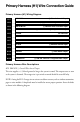
Primary Harness (H1) Wire Connection Guide Primary Harness (H1) Wiring Diagram H1/1 ___ ORANGE H1/2 ___ WHITE H1/3 ___ WHITE/BLUE H1/4 ___ BLACK/WHITE H1/5 ___ GREEN No Function H1/6 ___ BLUE No Function H1/7 ___ VIOLET No Function H1/8 ___ BLACK (-) Chassis Ground Input H1/9 ___ OPEN H1/10 ___ BROWN H1/11 ___ RED H1/12 ___ RED/WHITE (-) 500 mA Armed Output (+)/(-) Selectable Light Flash Output (-) Remote Start Activation Input (-) 200 mA Domelight Supervision Output No Wire (-)
IMPORTANT! Never interrupt any wire other than the starter wire. H1/2 WHITE (+/-) Selectable Light Flash Output As shipped, this wire should be connected to the (+) parking light wire. If the light flash polarity jumper is moved to the (-) position (see the Programming Jumper section of this guide), this wire supplies a (-) 200 mA output. This is available for driving (-) light control wires in Toyota, Lexus, BMW, some Mitsubishi, some Mazda, and other models.
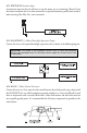
H1/3 WHITE/BLUE Activation Input A momentary input on this wire will start or stop the motor, just as transmitting Channel 3 from the remote transmitter does. It is often connected to an optional momentary push-button switch to make activating Valet Take Over more convenient. H1/4 BLACK/WHITE (-) 200 mA Domelight Supervision Output Connect this wire to the optional domelight supervision relay as shown in the following diagram: IMPORTANT! This output is only intended to drive a relay.
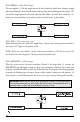
H1/10 BROWN (+) Horn Honk Output This wire supplies a (-) 200 mA output that can be used to honk the vehicle horn. It outputs a single pulse when locking the doors with the remote, and two pulses when unlocking with the remote. This wire will also output pulses for 30 seconds when the Panic Mode is activated. If the vehicle has a (+) horn circuit, an optional relay can be used to interface with the system, as shown below.
Secondary Harness (H2), Wire Connection Guide Secondary Harness (H2) Wiring Diagram H2/1 ___ GRAY/BLACK H2/2 ___ LIGHT GREEN/BLACK (-) Wait-to-Start Input (-) Factory Disarm/Special Accessory Secondary Harness Wire Descriptions H2/1 GRAY/BLACK (-) Diesel Wait-to-Start Bulb Input Connect this wire to the wire in the vehicle that sends the signal to turn on the WAIT-TO-START bulb in the dashboard.
H2/2 LIGHT GREEN/BLACK (-) Auxiliary Output This wire sends a negative pulse every time the remote start is activated. This can be used to pulse the disarm wire of the vehicle's factory anti-theft device. Use a relay to send a (-) or (+) pulse to the disarm wire as shown in the diagrams below. This wire can also be used as a special accessory output. (See Feature Descriptions section of this guide.
Heavy Gauge Relay Satellite Wire Descriptions RED (2) (+)12V Input for Relays Remove the two 30 amp fuses prior to connecting these wires and do not replace them until the satellite has been plugged into the control module. These wires are the source of current for all the circuits the relay satellite will energize. They must be connected to a high current source. Since the factory supplies (+) 12V to the key switch that is used to operate the motor, it is recommended that these wires be connected there.
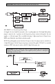
Remote Start Harness (H3), Wire Connection Guide Remote Start Harness (H3) Wiring Diagram 1 ___ BLUE (-) Status/Factory Security Rearm Output 2 ___ BLUE/BLACK (-) 200 mA Optional Third Ignition Output 3 ___ GRAY 4 ___ BROWN 5 ___ VIOLET/WHITE Tachometer Input Wire 6 ___ BLACK/WHITE (-) Neutral Safety Switch Input (-) Hood Pinswitch Shutdown Wire (-) Brake Switch Shutdown Wire Remote Start Harness Wire Descriptions H3/1 BLUE Status/Factory Security Rearm Output This wire supplies a 200mA ou
H3/4 BROWN (+) Brake Switch Input This wire MUST be connected to the vehicle's brake light wire. This is the wire that shows (+) 12V when the brake pedal is pressed. The remote start will be disabled or shut down any time the brake pedal is pressed. H3/5 VIOLET/WHITE Tachometer Input This input provides the module with information about the engine's revolutions per minute (RPMs). It can be connected to the negative side of the coil in vehicles with conventional coils.
Neutral Safety Switch Interface Some vehicles combine the column shift mechanism and the mechanical neutral safety switch into one mechanical part. In these vehicles, it is impossible to interface the remote start system before the neutral safety switch. With this type of vehicle, if the vehicle is left in a drive gear and the remote start system is activated, the vehicle will move and may cause damage to persons or property.
Door Lock Harness (H4), Wire Connection Guide H2/A ___ Green (-) Lock, (+) Unlock Output H2/B ___ Empty Unless Using 451M H2/C ___ Blue (-) Unlock, (+) Lock Output IMPORTANT! The door lock outputs are low current and should not be attached directly to any high current device; they are only to be used to activate relays NOTE: For detailed instructions about connecting to the vehicle’s power door lock systems, refer to the Door Lock Wiring guide (Document No.
Valet/Program Switch, 2-Pin BLUE Plug The Valet/Program button should be accessible from the driver’s seat. It plugs into the BLUE port on the side of the unit. Consider how the button will be used before choosing a mounting location. Check for rear clearance before drilling a 9/32-inch hole and mounting the button. Programmer Interface, 3-Pin Port The BLACK three-pin port is provided for programming of the unit.
Mounting the Receiver/Antenna Receiver/antenna position should be discussed with the vehicle owner prior to installation, since the antenna may be visible to the vehicle’s operator. The best location for the receiver/antenna is centered high on either the front or rear windshield. For optimal range, the antenna should be mounted vertically. It can be mounted horizontally in relation to the windshield or under the dashboard away from metal, but range will be diminished.
Programming Jumpers Light Flash Jumper This jumper is used to determine the light flash output. In the (+) position, the on-board relay is enabled and the unit will output (+)12V on the WHITE wire, H1/2. In the (-) position, the onboard relay is disabled. The WHITE wire, H1/2, will supply a 200 mA (-) output suitable for driving factory parking light relays. NOTE: For parking light circuits that draw 10 amps or more, the jumper must be switched to a (-) light flash output.
System Features Learn Routine The System Features Learn Routine dictates how the unit operates. Due to the number of steps, they have been broken up into two menus. It is possible to access and change any of the feature settings using the Valet/Program switch. However, this process can be greatly simplified by using the 998T Bitwriter. Any of the settings can be changed and then assigned to a particular transmitter, up to four, a feature called Owner Recognition.
5. Release. The Valet®/Program switch can now be released. For example, to program the arming mode from active to passive, within 10 seconds of turning the ignition off, select Menu One and press and release the Valet/Program switch once. Then press it again and hold it. The LED will flash in groups of one and the horn will honk once (if connected). While holding the Valet®/Program switch, press the unlock button. The LED will stop flashing and go out. The horn will honk twice if connected.
System Features Menus Menu #1 - Basic Features Items in bold text have been programmed to the default setting at the factory. Feature Number Default LED ON Setting (Press Channel 1) LED OFF Setting (Press Channel 2) 1-1 Active arming Passive arming 1-2 Chirps ON Chirps OFF 1-3 Ignition controlled door locks ON Ignition controlled door locks OFF 1-4 Active locking only Passive locking 1-5 0.8 second door lock pulses 3.
Feature Descriptions The features of the system are described below. Features that have additional settings that can be selected only when programming with the 998T Bitwriter are indicated by the following icon: Menu #1 - Basic Features 1-1 ACTIVE/PASSIVE ARMING: When active arming is selected, the starter kill will arm (if connected) only when the transmitter is used. When set to passive arming, the starter kill will arm (if connected) 30 seconds after the ignition key is turned off.
➤ ➤ ➤ ➤ ➤ Selecting instant validity will output a negative signal from the Channel 2 output immediately when the Channel 2 button is pressed and will continue until the button is released. The latched output selection will output a negative signal as soon as the Channel 2 button is pressed and will continue until the button is pressed again. The latched/reset with ignition output selection operates just like the latched output but will reset or stop when the ignition is turned on.
2-3 RUN TIME 12/24/60 MINUTES: This feature controls how long the engine will run before it “times out” and shuts down. Programmed to the default setting the engine will run for 12 minutes. If the 24- or 60-minute run time is desired, press the unlock button of the transmitter. The LED will blink two times for 24 minutes and three times for 60 minutes. 2-4 PARKING LIGHTS FLASHING/CONSTANT: In the default setting, the unit will flash the vehicle’s parking lights while remote started.
Transmitter/Receiver Learn Routine The system comes with two transmitters that have been taught to the receiver. The receiver can store up to four different transmitter codes in memory. Use the following learn routine to add transmitters to the system or to change button assignments if desired. If the system was previously programmed using the 998T Bitwriter, the learn routine may be locked.
Channels #4-66: Channels 4 through 6 are used to assign the arm, disarm and panic functions to separate buttons on the remote control. Teaching a button to Channel 4 erases all information about that remote from memory. Any auxiliary functions that are desired will have to be reprogrammed.
Transmitter Configurations The transmitters can be programmed with the standard or single button arm/disarm configurations by using the Auto Learn functions in the Transmitter/Receiver Learn Routine. Standard Configuration A remote that uses the standard configuration operates similarly to many factory keyless entry remotes. A standard configuration transmitter allows arming, disarming, and Panic Mode activation with separate buttons.
Tach Learning To learn the tach signal: 1. Start the vehicle with the key. 2. Within 5 seconds, press and hold the Valet/program switch. 3. The LED will light constant when the tach signal is learned. 4. Release the Valet/program switch. NOTE: A dim or pulsing LED when learning tach means the unit has not learned the tach signal. Test all connections, and if good, relocate the tach input wire and continue with tach learning procedure.
4. Release the Valet/program switch. 5. Press and release the Valet/program switch. The LED will now report the last system shutdown by flashing for one minute in the below grouped patterns; the LED will stop flashing when the ignition is turned on.
Safety Check Before vehicle reassembly, the remote system must be checked to ensure safe and trouble-free operation. The following test procedure must be used to verify proper installation and operation of the system. The installation must be completed before testing, including connection to the brake switch and hood switch. 1. Test the BRAKE shutdown circuit: With the vehicle in Park (P), activate the remote start system. Once the engine is running, press the brake pedal.
Troubleshooting The ignition comes on, but the starter will not crank. ➤ ➤ ➤ Does it start with the key in the ignition? If so, does the vehicle have a VATS Pass-Key system? Will it start with the brake pedal depressed? (Make sure to disconnect the brake shutdown when performing this test.) If so, it may have a brake/starter interlock. Is the correct starter wire being energized? Check by energizing it yourself with a fused test lead. The starter cranks for six seconds but does not start.
➤ ➤ ➤ Make sure the purple starter wire is connected on the starter side of the starter kill relay. Does the vehicle have an immobilizer? Some immobilizer systems will not allow the vehicle to crank if active. Check connections. The two red heavy gauge input wires on the relay satellite should have solid connections. "T-taps", or "scotch locks" are not recommended for any high current heavy gauge wiring. Also, if the vehicle has more than one 12-volt input wire, then connect one red wire to each.
Wiring Quick Reference Guide