DEI PVM-4210 DIRECTED ENERGY, INC. PVM-4210 ±950V Pulse Generator Module OPERATION MANUAL Directed Energy, Inc. 2401 Research Blvd., Ste.
DEI PVM-4210
DEI PVM-4210 Table Of Contents 1.0 Safety...........................................................................................................3 2.0 Overview .....................................................................................................3 3.0 Specifications..............................................................................................6 4.0 Connector Pin-Outs And User Adjustments................................................7 4.1 Polarity Reversal ................
DEI PVM-4210 ********** WARNING ********** SAFE OPERATING PROCEDURES AND PROPER USE OF THE EQUIPMENT ARE THE RESPONSIBILITY OF THE USER OF THIS SYSTEM. Directed Energy, Inc (DEI) provides information on its products and associated hazards, but it assumes no responsibility for the after-sale operation and safety practices. ALL PERSONNEL WHO WORK WITH OR ARE EXPOSED TO THIS EQUIPMENT MUST TAKE PRECAUTIONS TO PROTECT THEMSELVES AGAINST POSSIBLE SERIOUS AND/OR FATAL BODILY INJURY.
DEI PVM-4210 1.0 Safety The high voltage/high current nature of this device dictates the use of caution when operating or servicing this equipment. OBSERVE ALL SAFETY PRECAUTIONS LISTED BELOW. FAILURE TO DO SO COULD RESULT IN SERIOUS INJURY. Precautions: 1. The Pulser should be serviced only by personnel experienced in high voltage pulsed power systems. 2.
DEI PVM-4210 photomultiplier tubes. The exceptional pulse fidelity of the PVM-4210 will optimize the performance of any system in which it is used. The module provides two pulse output channels, controlled by a common control logic. When the control logic receives a gate signal, both channels pulse simultaneously. One channel pulses from ground to the positive high voltage, and the other channel pulses from ground to the negative high voltage.
DEI PVM-4210 P1-9 +5VDC +5V P1-15 P1-6 +24V Gate Pulse +24V To Logic +75V Power Supply +15V Gate Inversion on/off Pulse Generation Over current inhibit +950V Power Supply Positive Pull Up Positive Output On Primary Drive Transformer Off Positive Pull Down O/C P1-14 HV Enable To HV Power Supplies Overcurrent Sense Output Current Sense +/- Negative Pull Down Negative Output Negative Pull Up +24V Document Number 9100-0201 Rev 8 Directed Energy, Inc.
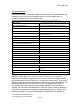
DEI PVM-4210 3.0 Specifications The pulser will meet or exceed the following specifications.
DEI PVM-4210 continuous pulse recurrence frequencies greater than 20KHz. This formula is not applicable when driving non-capacitive (resistive or inductive) loads. Contact DEI for information or assistance in using the PVM-4210 with different load characteristics or impedances. 4.
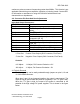
DEI PVM-4210 +5V GATE INPUT GROUND + PULSE VOLTAGE OUT + PULSE OUT GROUND GROUND - PULSE OUT - PULSE VOLTAGE OUT Output Pulse Configuration With Non-Inverted Gate Selected The ouput polarity can be reversed (so that the output is held at high voltage when the gate is low, and pulsed ground when the gate is high) by jumpering pins 10 and 11 together. This is shown in the figure below: Document Number 9100-0201 Rev 8 Directed Energy, Inc.
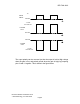
DEI PVM-4210 +5V GATE INPUT GROUND + PULSE VOLTAGE OUT + PULSE OUT GROUND GROUND - PULSE OUT - PULSE VOLTAGE OUT Output Pulse Configuration With Inverted Gate Selected 4.2 Power Supply Enable For safety and flexibility, the PVM-4210 features a power supply enable input (DSUB connector pin 14). In order to enable the DC power supplies (and therefore generate an output pulse), this input must be held HIGH. This can be done in two ways: 1. Apply a TTL high signal to pin 14.
DEI PVM-4210 5.0 OPERATING INSTRUCTIONS WARNING 1. Do not remove the input or output cables while the pulser is in operation. Never intentionally short-circuit the high voltage output of the pulser. Failure to observe these precautions can result in potential electric shock to personnel, arcing, and damage to the connectors and system. 4.
DEI PVM-4210 2. Connect the input DSUB connector, and connect the output to an appropriate load, prior to applying +24VDC power. 3. Monitor the voltage across the load, utilizing an appropriate high voltage probe or attenuator. 4. Apply +24VDC to +28VDC power to the module, and apply a TTL level power supply enable signal (or close the switch to connect pin 3 to pin 14 as described above).
DEI PVM-4210 -Input trigger voltage too low. -Input trigger pulse width too short. Increase width. -Input trigger frequency too high. Reduce frequency. -No input high voltage. Check HV supplies. -Enable circuit not satisfied. Ensure that +5VDC is applied to DSUB pin 14. -No gate polarity is selected. DSUB pins 9 & 10 or pins 10 &11 must be connected. -Output not connected correctly. Check all cables and connections. -Pulser is damaged. Contact DEI customer service. 6.
DEI PVM-4210 At DEI's discretion, DEI may elect to repair or replace the equipment claimed to be defective or refund the original purchase price, plus taxes and transportation charges incurred by the purchaser. This Warranty shall not apply to any product that has been: 1. Repaired, worked on, or altered by persons unauthorized by DEI; 2. Subjected to misuse, neglect, or damage by others; or 3.
DEI PVM-4210 APPENDIX Mechanical Dimensions And Mounting Hole/Connector Location Drawing Document Number 9100-0201 Rev 8 Directed Energy, Inc.
DEI PVM-4210 11.50 10.50 1.00 DEI + HV ADJUST PVM-4210 +/- 950V DUAL OUTPUT PULSER MODULE - HV ADJUST DB-15 PINOUT 2 3 6 7 9 10 11 12 14 15 5.80 5.00 4.30 + PULSE OUT + 950V MAX GROUND +5VDC @ 50mA OUTPUT GATE (TTL into 50 Ohms) +24VDC RETURN (GROUND) JUMPER TO PIN 10 FOR NON-INVERTING GATE / OUTPUT POLARITY SELECT JUMPER TO PIN 10 FOR INVERTING GATE RETURN (GROUND) POWER SUPPLY ENABLE/DISABLE (TTL HIGH = ENABLED) +24-28VDC @ 600mA MAX CAUTION, RISK OF ELECTRIC SHOCK 4.