
Installation guide


© 2006 directed electronics
9
h2/3 black/white domelight supervision input (87)
This wire determines the output of the BLACK/WHITE H1/15 wire on the main 18-pin
harness. If the vehicle has a negative domelight circuit, ground this wire; if the vehi-
cle has a positive domelight circuit, attach this wire to a 12 volt constant source.
h2/4 brown/red brake light (+) 12V input
This is the polarity source for the brake light output and must be 12 volt constant.
h2/5 brown/white brake light output
This wire powers the brake light circuit with the 12 volt circuit only on H2/10
when activated.
h2/6 blue/white second unlock output (200mA)
This wire produces a (-) 200mA output for progressive locks in which the driver door
unlocks first and the remaining locks unlock with a second press of the unlock button.
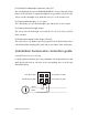
immobilizer harness wire connection guide
immobilizer harness wiring
Locate the ignition and starter wires using a multimeter. Cut the appropriate wire and
attach the key side and car side wires to the corresponding wires on the four-pin
immobilizer harness.
H3/4 Ignition Car Side
H3/3 Ignition Key Side
H3/2 Starter Key Side
H3/1 Starter Side
x
CUT
x
CUT
Starter
Ignition