
User manual

Garrecht Avionik GmbH TRX-1500 ADS-B Traffic Monitor User Manual
Revision: 1.0a 17 31 JAN 2012
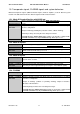
2.4.4.1. Use of interface ports
Port -# Funktion
1 Power supply, NMEA output for supplying Mode-S transponders
2 CDTI 1, Interface 1 for cockpitdisplay (compatible to FLARM extended displays )
3 CDTI 2, Interface 1 for cockpitdisplay (compatible to FLARM extended displays or
GARMIN GPS TIS compatible device), configuration via TRX-Tool
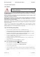
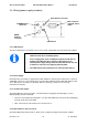
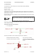
2.4.4.2. Pinout of the TRX-1500 main connector
View TRX-1500 Main connector (pins) = view soldering female connector
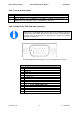
Pinbelegung Sub-D 15HD Stecker (CN-1)
Pin #
Funktion
1 + 3V3 DC out
2 GND
3 Audio out
4 Port 3 RX
5 Port 2 RX
6 + 3V3 DC out
7 GND
8 Port 3 TX
9 Port 2 TX
10 Port 1 TX
11
+9 ... + 32V DC, USE A FUSE (0,5 A)
12 GND
13 n.c. (reserved for future applications)
14 n.c. (reserved for future applications)
15 Port 1 RX
Wiring of the 15 pin HD D-
Sub connector has to be carried out properly to
prevent shorts and resulting damage to the device and/or connected displays.
If specific skills or required tools are missing, please consult your avionic
s
workshop for assistance.