
User manual

Garrecht Avionik GmbH TRX-1500 ADS-B Traffic Monitor User Manual
Revision: 1.0a 16 31 JAN 2012
2.4. Wiring (power supply and data)
2.4.1. USB interface
The unit's USB interface is intended to be used for system configuration via PC and TRX-Tool software.
2.4.2. Power Supply
Electrical power (9-32 V DC) is supplied to the TRX-1500 via a common power and interface connector
(TRX Main connector). To prevent damage to your aircraft installation and the TRX-1500, always install
a fuse. Missing fuse or wrong fuse dimension will cause damages, which are not covered by
manufacturers warranty.
2.4.3. 3V3 DC Power output
The TRX-1500 main connector provides a 3V3 DC output for supplying external displays (such as
Butterfly Display or Flarm V2/V3/V4).
• Do not feed electrical power through the 3.3V pins TRX-1500 main connectorto avoid damaging
internal circuits of the TRX-1500.
• Max. outout current of the internal 3.3V converter: 0,5 A
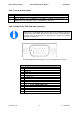
2.4.4. Data interfaces (Port-1 to Port-3)
The TRX-1500 provides data interfaces, which can be configured using the TRX-Tool PC software.
•
Before the first time connection of the TRX-1500 to your PC , the
TRX-Tool needs to be installed properly!
• As the output power of the PC USB port might be insufficient for
powering the TRX-1500. the system must be powered via an
external power supply
during communication with the PC. Use one
of the RJ-45 connectors for supplying external power.
• The TRX-1500 must be switched on for communication with PC
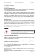
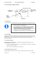
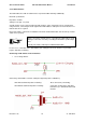
USB inteface
ADS
-
B
Antenna
connector
Main connector
serial I/O, Power,
Audio
GPS Antenna conncetor
FLARM
-
Antenne
connector