
Goodman AVPTC Installation Instructions ComfortBridge

5
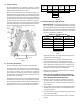
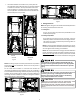
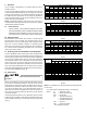
7. The boom le drain connecon is the primary drain for
this applicaon and condensate drain line must be aached
to this drain connecon. The top connecon of the three
drain connecons on the drain pan must remain plugged
for this applicaon. The boom le drain connecon is for
the secondary drain line (if used).
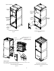
UPFLOW DOWFLOW
UPFLOW DOWFLOW
Figure 2 Figure 3
NOTE: If removing only the coil access panel from the unit, the lter
access panel must be removed rst. Failure to do so may result in
panel damage.
Do not install the air handler in a location that violates the
instrucons provided with the condenser. If the unit is located in
an uncondioned area with high ambient temperature and/or high
humidity, the air handler may be subject to nuisance sweang of
the casing. On these installaons, a wrap of 2” berglass insulaon
with a vapor barrier is recommended.
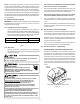
HORIZONTAL LEFT
Figure 4
HORIZONTAL RIGHT
Figure 5
7 Refrigerant Lines
NOTE: Refrigerant tubing must be routed to allow adequate access
for servicing and maintenance of the unit.
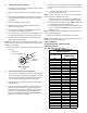
7.1 TubingSize
For the correct tubing size, follow the specicaon for the
condenser/heat pump.
7.2 TubingPreparaon
All cut ends are to be round, burr free, and clean. Failure to
follow this pracce increases the chances for refrigerant leaks.
The sucon line is spun closed and requires tubing cuers to
remove the closed end.
NOTE: To prevent possible damage to the tubing joints, do not
handle coil assembly with manifold or owrator tubes. Always
use clean gloves when handling coil assemblies.
NOTE: The use of a heat shield is strongly recommended when
brazing to avoid burning the serial plate or the nish of the unit.
Heat trap or wet rags must be used to protect heat sensive
components such as service valves and TXV valves sensing bulb.
This product is factory-shipped with R410A and dry
nitrogen mixture gas under pressure. Use appropriate
service tools and follow these instructions to prevent
injury.
A quenching cloth is strongly recommended to prevent
scorching or marring of the equipment finish when
brazing close to the painted surfaces. Use brazing
alloy of 5% minimum silver content.
Applying too much heat to any tube can melt the tube. Torch
heat required to braze tubes of various sizes must be
proportional to the size of the tube. Service personnel must
use the appropriate heat level for the size of the tube being
brazed.
CAUTION