
Goodman AVPTC Installation Instructions ComfortBridge

14
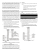
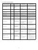
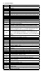
ModelM AX CFM
AVPTC25B14
AVPTC29B14
AVPTC35B14
AVPTC37B14
1200
AVPTC33C14 1300
AVPTC31C14
AVPTC37C14
AVPTC39C14
1600
AVPTC37D14
AVPTC49C14
1800
AVPTC49D14
AVPTC59C14
1900
AVPTC59D14
AVPTC61D14
2100
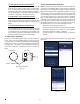
5. Use the Cool Cloud HVAC phone applicaon to congure/
test air handler operaons.
NOTE: The phone applicaon cannot test a non- communicang
outdoor unit. The thermostat will be required for outdoor unit
tesng.
17.1 ElectricHeaterKitTesng
1. Select the electric heat icon aer entering the air handler
menus while using the Cool Cloud phone applicaon.
2. Select any value less than 50% for low stage operaon and
any value greater than 50% for high stage operaon.
3. Conrm thermostat heang and cooling calls funcon
properly for high stage operaon.
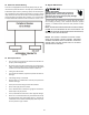
18 Dehumidicaon
Dehumidicaon allows the air handler’s circulator blower to
operate at a reduced speed during a combined thermostat call
for cooling and a dehumidicaon call from the thermostat or
humidistat. This lower blower speed increases dehumidicaon
of the condioned air as it passes through the indoor coil. The
control board is equipped with a 24 volt dehumidicaon input
(DH) located on the thermostat wiring connector. The terminal
can be congured to enable dehumidicaon when the input is
energized or de-energized. When using an external dehumidistat,
connect it between the R and DH terminals. If the humidistat
closes on humidity rise or the thermostat energizes this terminal
when dehumidifcaon is required, set the control board Dehum
Logic Menu () to “” using the push buons or Cool Cloud
HVAC phone applicaon. If the humidistat opens on humidity or
the thermostat de-energizes this terminal when dehumidicaon
is required, set the Dehum Logic Menu to “” using the push
buons or Cool Cloud HVAC phone applicaon.
19 Auxiliary Alarm Switch
The control is equipped with a 24VAC Aux Alarm to be
used for a condensate switch install (designated by CON-DENSATE
IN/OUT on the control). By default, the connected
AUX switch is normally closed and opens when the
water level in the evaporator coil base pan reaches an
undesirable level. The control responds by displaying a “” error
code and turning o the outdoor condensing
unit. If the AUX switch is detected to be in the closed
posion for 30 seconds, normal operaon resumes and
the error message is no longer displayed.
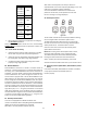
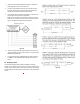
20 Start-Up Procedure
Figure 20
The air handler includes three on-board push buons allowing
users to navigate indoor and outdoor system menus.
The Right and Le buons allow the user to scroll through
the main menus and to then scroll through available opons
within specic menus. The Center buon is used to
enter into a main menu and to then permanently select
opons within those menus.
NOTE: Aer scrolling to the desired opon within a menu,
that opon may be ashing on the 7-segment displays.
This indicates the opon has not been ocially selected.
Pressing the Center buon two mes will select that
opon. The rst press will stop the ashing. The second
will make the selecon ocial and return you to the main menu.
21 AccessoryControl(Humidiers,Dehumidiers,Ven-
lators)
If an external humidier, dehumidier or venlator is installed,
it may require airow from the HVAC system to
funcon properly.