
Goodman AVPTC Installation Instructions ComfortBridge

8
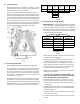
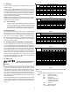
SUCTION PRESSURE
PSIG R-22 R-410A
50 26 1
52 28 3
54 29 4
56 31 6
58 32 7
60 34 8
62 35 10
64 37 11
66 38 13
68 40 14
70 41 15
72 42 16
74 44 17
76 45 19
78 46 20
80 48 21
85 50 24
90 53 26
95 56 29
100 59 31
110 64 36
120 69 41
130 73 45
140 78 49
150 83 53
160 86 56
170 90 60
SATURATED SUCTION PRESSURE
TEMPERATURE CHART
SATURATED SUCTION
TEMPERATURE ºF
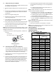
8 CondensateDrainLines
The coil drain pan has a primary and a secondary drain with 3/4”
NPT female connecons. The connectors required are 3/4” NPT
male, either PVC or metal pipe, and should be hand ghtened to
a torque of no more than 37 in-lbs. to prevent damage to the drain
pan connecon. An inseron depth of approximately 3/8” to 1/2”
(3-5 turns) should be expected at this torque.
1. Ensure drain pan hole is not obstructed.
2. To prevent potenal sweang and dripping on to nished
space, it may be necessary to insulate the condensate drain
line located inside the building. Use Armaex
®
or similar
material.
A secondary condensate drain connecon has been provided for
areas where the building codes require it. Pitch all drain lines a
minimum of 1/4” per foot to provide free drainage. Provide required
support to the drain line to prevent bowing. If the secondary drain
line is required, run the line separately from the primary drain and
end it where condensate discharge can be easily seen.
NOTE: Water coming from secondary line means the coil primary
drain is plugged and needs immediate aenon.
CAUTION
If secondary drain is not installed, the secondary
access must be plugged.
Insulate drain lines located inside the building or above a nished
living space to prevent sweang. Install a condensate trap to ensure
proper drainage.
NOTE: When units are installed above ceilings, or in other
locations where damage from condensate overow may occur,
it is MANDATORY to install a eld fabricated auxiliary drain
pan under the coil cabinet enclosure.
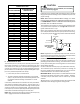
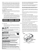
The installaon must include a “P” style trap that is located as close
as is praccal to the evaporator coil. See Figure 12 for details of a
typical condensate line “P” trap.
NOTE: Units operang in high stac pressure applicaons may re-
quire a deeper eld constructed “P” style trap than is shown in Fig-
ure 12 to allow proper drainage and prevent condensate overow.
Air Handler
3" MIN.
POSITIVE LIQUID
SEAL REQUIRED
AT TRAP
Drain
Connection
2" MIN.
Figure 11
NOTE: Trapped lines are required by many local codes. In the ab-
sence of any prevailing local codes, please refer to the requirements
listed in the Uniform Mechanical Building Code.
A drain trap in a draw-through applicaon prevents air from be-
ing drawn back through the drain line during fan operaon thus
prevenng condensate from draining, and if connected to a sewer
line to prevent sewer gases from being drawn into the airstream
during blower operaon.
Use of a condensate removal pump is permied when necessary.
This condensate pump should have provisions for shung o
the control voltage should a blocked drain occur. A trap must be
installed between the unit and the condensate pump.
IMPORTANT NOTE: The evaporator coil is fabricated with oils that
may dissolve styrofoam and certain types of plascs. Therefore,
a removal pump or oat switch must not contain any of these
materials.
Tip: Priming the “P” trap may avoid improper draining at the inial
installaon and at the beginning of the cooling season.