
Goodman AVPTC Installation Instructions ComfortBridge

7
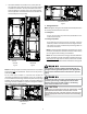
7.3 TubingConneconsforTXVModels
TXV models come with factory installed TXV with the bulb
pre-installed on the vapor tube.
1. Remove refrigerant tubing panel or coil (lower) access pan-
el.
2. Remove access valve ng cap and depress the valve stem
in access ng to release pressure. No pressure indicates
possible leak.
3. Replace the refrigerant tubing panel.
4. Remove the spin closure on both the liquid and sucon
tubes using a tubing cuer.
5. Insert liquid line set into liquid tube expansion and slide
grommet about 18” away from braze joint.
6. Insert sucon line set into sucon tube expansion and slide
insulaon and grommet about 18” away from braze joint.
7. Braze joints. Quench all brazed joints with water or a wet
rag upon compleon of brazing.
NOTE: The sensing bulb must be permanently located. A heat
shield, heat trap, or wet rag must be used during brazing to prevent
damage to the TXV valve.
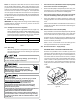
8. Replace access panels, sucon line grommet, insulaon and
all screws.
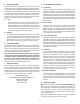
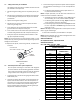
RUBBER
GROMMET
SUCTION LINE
WITH SPIN CLOSURE
SuconLineGrommet
Figure 10
7.4 ThermalExpansionValveSystemAdjustment
Run the system at Cooling for 10 minutes unl refrigerant
pressures stabilize. Use the following guidelines and meth-
ods to check unit operaon and ensure that the refrigerant
charge is within limits. Charge the unit on low stage.
1. Purge gauge lines. Connect service gauge manifold to base-
valve service ports.
2. Temporarily install a thermometer on the liquid line at the
liquid line service valve and 4-6’’ from the compressor on
the sucon line. Ensure the thermometer makes adequate
contact and is insulated for best possible readings. Use
liquid line temperace to determine subcooling and vapor
temperature to determine superheat.
3. Check subcooling and superheat. Systems with TXV applica-
on should have a subcooling of 7 to 9°F and superheat of
7 to 9°F
a. If subcooling and superheat are low, adjust TXV to 7 to
9°F, and then check subcooling.
NOTE: To adjust superheat, turn the valve stem clockwise to in-
crease and counter clockwise to decrease.
b. If subcooling is low and superheat is high, add charge to
raise subcooling to 7 to 9°F, and then check superheat.
c. If subcooling and superheat are high, adjust TXV valve to
7 to 9° superheat, then check subcooling.
d. If subcooling is high and superheat is low, adjust TXV valve
to 7 to 9° superheat and remove charge to lower the sub-
cooling to 7 to 9°F.
NOTE: Do NOT adjust the charge based on sucon pressure unless
there is a gross undercharge.
4. Disconnect manifold set, and installaon is complete.
NOTE: Check the Schrader ports for leaks and ghten valve cores
if necessary. Install caps nger-ght.
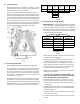
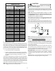
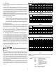
SUBCOOL FORMULA=
SAT. LIQUID LINE TEMP - LIQUID LINE TEMP
SUPERHEAT FORMULA=
SUCT. LINE TEMP - SAT. SUCT. TEMP
SUCTION PRESSURE
PSIG R-22 R-410A
50 26 1
52 28 3
54 29 4
56 31 6
58 32 7
60 34 8
62 35 10
64 37 11
66 38 13
68 40 14
70 41 15
72 42 16
74 44 17
76 45 19
78 46 20
80 48 21
85 50 24
90 53 26
95 56 29
100 59 31
110 64 36
120 69 41
130 73 45
140 78 49
150 83 53
160 86 56
170 90 60
SATURATED SUCTION PRESSURE
TEMPERATURE CHART
SATURATED SUCTION
TEMPERATURE ºF