
User Manual


6
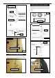
See below pictures. Make yourself the tem-
plate of your engine on paper.
Mark and drill 4 holes for engine mount.
Insert 4 blind nuts to rewall.
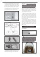
Control horn M3
Aluminum washer.
Rudder
Fuselage
Aluminum washer.
Epoxy.
M3 Lock nut.
Epoxy.
Rudder.
Fuselage
18mm
ENGINE MOUNT INSTALLATION.
.
M4x30mm
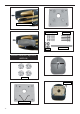
INSTALLING THE STOPPER
ASSEMBLY.
1) Using a modeling knife, carefully cut
o the rear portion of one of the 3 nylon
tubes leaving 1/2” protruding from the
rear of the stopper. is will be the fuel
pick up tube.
Rudder control horn.
read locker glue.
Using the same techniques used aileron
control horn. See picture below.
RUDDER CONTROL HORN.
M3x45mm
2 sets.