
User Manual


77
AILERON LINKAGE.
Repeat the procedure for the other wing
half.
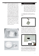
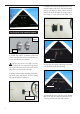
1) Using a ruler & pen to draw a straight line
as below picture.
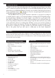
2) Locate the two nylon control horns, two
nylon control horn backplates and four ma-
chine screws.
3) Position the aileron horn on the bottom
side of aileron. e clevis attachment holes
should be positioned over the hinge line.
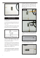
Control Horn.
Mounting Screws.
Mounting Plate.
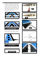
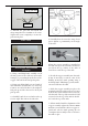
7) With the aileron servo centered and the
aileron even with the trailing edge of the
wing attach the clevis to the control horn.
Mark the control wire where it crosses the
servo arm hole.
Mark point.
Pen.
Cut.
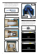
8) Make a 90-degree bend at the mark and
cut o the excess wire leaving 10mm past the
bend.
4) Using a 1mm drill bit and the control
horns as a guide, drill the mounting holes
through the aileron halves.
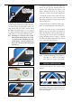
5) Mount the control horns by inserting the
screws through the control horn bases and
aileron halves, then into the mounting back-
plates. Do not overtighten the screws or the
backplates may crush the wood.
6) read one nylon adjustable control horn
onto each aileron control rod. read the
horns on until they are ush with the ends of
the control rods.
9) Connect the linkage as shown and secure
the control wire with a wire keeper.