
User guide

4 OF 4
INSTALLATION SHEET
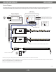
System Diagram
The following diagram is provided as an example system design. CAT5 (RJ45 connecons) data cables are the most cost-eecve soluon for
transming DMX-512 signals. XLR-3 cables may also be installed but require an addional adapter for connecng to DMX decoders. Always review
each component installaon guide for detailed and up-to-date wiring instrucons. Install in accordance with NEC and local regulaons.
V+
V-
V+
CH1 - R
CH2 - G
CH3 - B
CH4 - W
0-5 0-9
0-9
Data IN
Data OUT
V+
V-
V+
CH1 - R
CH2 - G
CH3 - B
CH4 - W
0-5 0-9
0-9
Data IN
Data OUT
G
+
-
Data Output
to DMX Decoder
Power
Input
AC Power
50/60Hz
L
N
Class 2 Low Voltage Driver**
Installed in Junction Box
‡
G*
N
L
Input
Output
V+
V-
DMX Controller
Installed in Wall Box
‡
CAT5 Data Cable (RJ45 Connections)
Power input of DMX controllers may vary.
See DMX controller specifications to ensure
appropriate high or low voltage power input.
DMX Decoder
DMX Decoder
V- V+
V- V+
RGBW Strip Light / Fixture
‡‡
RJ45 Coupler
RJ45 Splice Cable
V+ V+
CH1 R
CH2 G
CH3 B
CH4 W
V+ V+
CH1 R
CH2 G
CH3 B
Install applicable wire gauge / type
CH4 - W connection only utilized for RGBW / RGB(X) installation.
Wall Washer / DMX-512 Fixture
‡‡
AC Power
50/60Hz
Female RJ45 / XLR-3 Adapter
RGB Strip Light / Fixture
‡‡
RJ45 Splice Cable
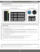
Wiring Connections
Brown Ground
White/Orange Data +
Orange Data -
* Driver may not require a fault ground connecon. Refer to driver specicaons for addional informaon.
** Install a compable Class 2 constant voltage driver. It is recommended to load the driver no more than 80% its labeled rang for maximum longevity.
‡ Refer to driver specicaons for a compable juncon box.
‡‡ See xture specicaons for maximum series run limits.
WALL MOUNT DMX CONTROLLER
V 1.0