
User guide

3 OF 4
INSTALLATION SHEET
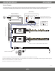
Pinout Connecon Guide
The following diagrams/tables indicate the appropriate connecons for patching your own CAT5/RJ45, and XLR-3 splice cables. These diagrams
are for general reference and may slightly dier between dierent cable manufacturers.
Troubleshoong
For thorough troubleshoong of LED strip light and xtures, see LED xture installaon guides.
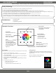
LED xtures not responding to touch
1. Ensure the blue indicator light is on by pressing ‘Power.’ The indicator light will blink rapidly when pressing/holding any key on the touch pad.
2. Ensure the appropriate zone number was pressed prior to controlling the DMX decoder/xture. For example, if you know the xture is addressed
to zone 1, press ‘1’ prior to controlling.
3. Ensure the individual zone has not been turned o. Long pressing zones 1-4 will turn the specic zone ON/OFF. Addionally, long pressing R, G, B,
W will increase/decrease individual brightness and short pressing will turn R, G, B, W ON/OFF.
4. Ensure the DMX decoder/xture is addressed properly. For example, address ‘001’ will respond to zone 1 of the controller. See ‘Seng the DMX
Address’ for addional addressing informaon.
LED xture responding incorrectly
Ensure all wiring connecons are correct. Reversing the Data + and Data - will cause lights to icker and not respond to controller.
5. Power connecons of all components (drivers, DMX decoders/xtures, DMX controller).
6. DMX Data connecons - See ‘Pinout Connecon Guide’ and ‘System Diagram’ for RJ45 hard-wiring connecons.
7. DMX decoder PWM output connecons – See ‘System Diagram’ for CH 1-4 connecons.
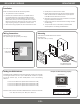
WALL MOUNT DMX CONTROLLER
For addional quesons and concerns regarding installaon or operaon of this product, please contact technical support.
Please have all product part numbers on hand for fast and ecient technical assistance.
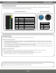
RJ45 568B Connecon Pinout
1 2 3 4 5 6 7 8
RJ45 568B Pinout Table
Pin No. Wire Color Funcon
1 White/Orange Data +
2 Orange Data -
3 White/Green None
4 Blue None
5 White/Blue None
6 Green None
7 White/Brown May be used as 2nd ground
8 Brown Ground
XLR-3 Pinout Table
Pin No. Funcon
1 Ground
2 Data -
3 Data +
XLR-3 Connecon Pinout