
Owner manual

2 OF 3
INSTALLATION SHEET
Independent Setup: (Primary xture operang independently or commanding addional xtures)
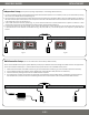
1. Link each wall washer together with the aached male and female XLR-3 cables (maximum run: 10 xtures). Power up each wall washer by inserng
the AC cord into a 120VAC electrical receptacle (Fig. 2a).
2. Once powered, the on-board control pad of each wall washer will automacally set to the Address Menu. Choose the preferred xture to operate as
the master controller (this can be any xture in the series) and set the code in the Address Menu of the master xture to the default address ‘001’. Do
so by seng Fields 1 & 2 to ‘0’ and Field 3 to ‘1’.
3. In the master wall washer Funcon (P) Menu (Fig. 2a), set the desired command for all master & slave xtures to perform in Fields 2 & 3. Once
selected, wait 10 seconds for the selected eld to stop ashing and the selected command will be set
4. To sync the slave washers to the master washer, set the code in the Address Menu of each slave xture to any number other than ‘001’ (Fig. 2b). It
is recommended to set each slave with an individual code (e.g. ‘002’, ‘003’, ‘004’ etc.). The Funcon (P) Menu is not required to operate slave wall
washers.
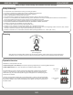
INDOOR WALL WASHERS
DMX Controller Setup: (One or more wall washers commanded by a DMX controller)
Please note that all DMX control systems operate dierently and may require addional technical knowledge of the DMX controller and equipment to
operate the wall washers eecvely. It is recommended that only experienced technicians install DMX control systems.
1. Aach the rst wall washer to the DMX controller using one of the aached XLR-3 cables (Fig. 3) (not all controllers have XLR-3 connecons).
2. Link each addional wall washer together with the aached male and female XLR-3 cables (maximum run: 10 xtures).
3. Power each xture by inserng the AC cord into a 120VAC electrical receptacle.
4. Once powered, the on-board control pad of each wall washer will automacally set to the Address Menu. To eecvely command the xtures
with the DMX control, match the value of each addressing eld with the 3-channel address code commanded from the DMX controller.
A B
A B
Fig. 2b
Fig. 2a
002
P63
A B
001
DMX Controller with
3-pin XLR Plugs
Fig. 3