
User guide

Page 2 of 3
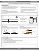
12V 300W CLASS 2 MAGNETIC DIMMABLE DRIVER INSTALLATION GUIDE
System Diagrams
The following diagrams are provided as example system designs. Use the Orange Boost Tap as an oponal voltage boost in place of the Black (Line)
wire if the xture is receiving noceable light degradaon. Cap the exisng hot wire not in use. Install in accordance with the NEC and local regulaons.
Traveling
Lines
Install applicable
wire gauge / type
– 1 + – 2 + – 3 +
– 4 + – 5 + – 6 +
1 2 3
4 5 6
AC Power
50/60Hz
N
L
120VAC Magnetic Low
Voltage Dimmer
†
Multi-Tap Magnetic
Dimmable Driver
LED Strip Light / Fixture
‡‡
B
L N GND
V-
V+
V-
V+
3-Way On/Off Switch
L
N
GND GND
Install applicable
wire gauge / type
– 1 + – 2 + – 3 +
– 4 + – 5 + – 6 +
1 2 3
4 5 6
AC Power
50/60Hz
N
L
120VAC Magnetic Low
Voltage Dimmer
†
Multi-Tap Magnetic
Dimmable Driver
B
L N GND
L
N
GND
LED Strip Light / Fixture
‡‡
V-
V+
V-
V+
Install applicable
wire gauge / type
– 1 + – 2 + – 3 +
– 4 + – 5 + – 6 +
1 2 3
4 5 6
AC Power
50/60Hz
N
L
Multi-Tap Magnetic
Dimmable Driver
B
L N GND
L
N
GND
LED Strip Light / Fixture
‡‡
V-
V+
V-
V+
120VAC On/Off Switch
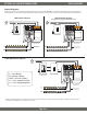
L = Line (Black)
N = Neutral (White)
GND = Ground (Green)
V+ = Low Voltage Positive
V- = Low Voltage Negative
ON/OFF Switch Diagram
(Only applies to this specic model dimmable driver)
MLV Dimmer Diagram
3-Way MLV Dimmer Diagram
† Install a compable magnec low voltage dimmer switch. See dimmer switch manufacturer installaon guide for complete wiring instrucons.
‡‡ See xture specicaons for maximum series run limits.