
User Manual


Table Of Contents
Torque “BC” Spring Shaft Length Magnet Gap “A”
Model Number Lb. Ft. +1/32 -.000 Length “D” “AH” Max. A-Min. A-Max.
R71010-9 10 5/8 1-5/16 3-7/16 .030 .062
R71015-9 15 5/8 1-5/16 3-7/16 .030 .062
R72025-9 25 5/8 1-5/16 3-3/4 .030 .062
R73035-9 35 5/8 1-5/16 4-3/8 .035 .062
R74050-9 50 5/8 1-5/16 5-1/8 .035 .062
R75075-9 75 5/8 1-5/16 5-1/8 .045 .062
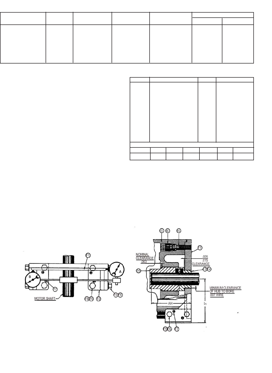
INSTALLATION OF FOOT MOUNTING
BRAKE (See Tables 4, 5 & Figure 5)
9. Install bracket (F1) over motor shaft extension and half-
tighten capscrews (F8). The distance from the mounting face
of the bracket (F1) to end of motor shaft must not exceed
dimension “AH” max. (Table 5).
10. Clamp dial indicator “A” to motor shaft and position bracket
(F1) with shims as necessary, by tapping with a soft mallet
until dial indicator does not read over .002” total change in
one full revolution of the shaft. Move dial indicator to “B”
and position bracket until dial indicator does not read over
.004” total change in one full revolution of shaft.
11. Draw all bolts up tight. Recheck alignment with dial indicator.
Readjust if necessary until tolerances are within limits with all
bolts tight. Drill eight 1/4” dia. holes into mating parts and
drive dowel pins (F7) into place.
12. Mount stop bushing (F3) on shaft with clearance of .005” to
.015” between bushing and bracket (F1). Mount hub (14) on
shaft butting firmly against stop bushing. Complete mounting
of brake per paragraphs 2 through 6.
WEAR ADJUSTMENT (See Figure 2 & Table 4)
13. The magnet gap “A” increases as the friction discs wear.
When magnet gap measures “A-Max,” adjust to “A-Min”
using gap adjusting nuts (2) and (4). Magnet gap must never
exceed “A-Max” and must be adjusted periodically.
ITEM DESCRIPTION QTY PART NUMBER
F1 Foot Mtg. Bracket 1 K070066-001
F2 Foot Pad 2 G070180-001
F3 Stop Bushing 1 G070181-*
F4 Set Screw 2 W002001-013
F5 Hx. Hd. Cap Screw 4 W001007-055
F6 Split Lockwasher 8 W004006-008
F7 Roll Pin 8 W005003-170
F8 Hx. Hd. Cap Screw 4 W001007-058
14 Hub 1 H070044-*
15 Mounting Bolt 4 W001013-132
16 Locking Screw 4 W002002-001
*Specify bore
MODEL 71010 71015 72025 73035 74050 75075
“AH” 4-3/4 4-3/4 5-1/16 5-11/16 6-7/16 6-7/16
Table 4. Adjustments
Table 5. Foot Mounting Parts
Figure 5.
6