
Use and Care Manual


13
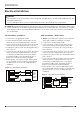
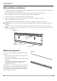
Power Cord Installation
WARNING: Power cord option is only suitable for
120V installations.
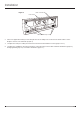
1. Remove the 3 screws that secure the pre-installed
hardwire plate.
2. Connect the black L1 wire from the unit to the black
wire of the plug kit.
3. Connect the white N wire from the replace to the
white wire from the plug kit.
4. Terminate the yellow L2 wire from the replace with a
wire connector.
5. Connect green G wire from the replace to the green
wire from the plug kit.
6. Ensure all wire connections are tight and that wires
are secured with wire ties and do not protrude past
the ame panel, so as not to be visible after nal
installation.
7. Secure the power cord’s pre-installed cover plate
using the screws removed when removing the
hardwire plate. The previously removed electrical
cover plate can be disposed of.
WARNING: This heater is not intended for use with
an extension cord. Plug the cord directly into an
appropriate grounded receptacle.
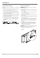
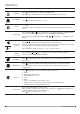
240V Hardwire Installation
You will need a 4-wire240 V supply (L1, L2, Neutral, and
Ground).
1. Connect the black L1 wire from the unit to the L1 wire
from the power supply with a wire connector.
2. Connect the yellow L2 wire from the unit to the L2
wire from the power supply with a wire connector.
3. Connect the white N wire from the unit to the neutral
wire from the power supply.
4. Connect the green G wire from the unit to the ground
wire from the power supply with a wire connector or
attach the grounding wire.
5. Ensure all wire connections are tight and that wires
are secured with wire ties and do not protrude past
the ame panel, so as not to be visible after nal
installation.
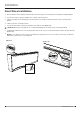
Installation
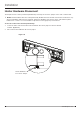
Figure 8
FIREPLACE JUNCTION BOX
Green - Ground
Green - Ground
White - Neutral
White - Neutral
Black - L
Black - L1
Red - L2
120 V
POWER
SUPPLY
(BREAKER
PANEL)
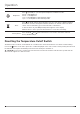
FIREPLACE JUNCTION BOX
240 V
POWER
SUPPLY
(BREAKER
PANEL)
RED
–
L2
Green - Ground
Green - Ground
White - Neutral
White - Neutral
Black - L
Black - L1
Red - L2
YELLOW- L2
240 V Hardwire Installation
Figure 9