CE MOUNTING and OPERATING MANUAL Water-to-Water Heat Pump for Indoor Installation WI WI WI WI Order No.: 452230.67.
CONTENTS 1 READ IMMEDIATELY 1.1 1.2 1.3 Important Information Legal Provisions and Directives Energy-Efficient Use of the Heat Pump 2 PURPOSE OF THE HEAT PUMP 3 4 2.1 2.2 Application Principle of Operation 3 BASELINE UNIT 4 4 TRANSPORT 5 5 INSTALLATION 5 5.1 5.2 General Information Sound Emissions 6 MOUNTING 6.1 6.2 6.3 6.4 General Heating-Side Connection Heat Source-Side Connection Electrical Connection 7 COMMISSIONING 7.1 7.2 7.
READ IMMEDIATELY 1 READ IMMEDIATELY 1.1 Important Information CAUTION! The well water must meet the required water quality standards. CAUTION! The heat pump is not attached to the wooden pallet. CAUTION! The heat pump must not be tilted more than max. 45 ° (in either direction). CAUTION! Do not lift unit by the holes in the panel assemblies! CAUTION! Flush the heating system prior to connecting the heat pump.
PURPOSE OF HEAT PUMP BASELINE UNIT 2 PURPOSE OF THE HEAT PUMP 3 BASELINE UNIT The water-to-water heat pump is designed for use in existing or newly built heating systems. Water, which can be supplied from wells, or the like, is used as the heat carrier. The baseline unit consists of a heat pump, ready for connection, for indoor installation, complete with housing, control panel and integrated controller. The refrigeration cycle contains the refrigerant R407C.
TRANSPORT MOUNTING 4 TRANSPORT A lift truck is suited for transporting the unit on a level surface. If the heat pump needs to be transported on an uneven surface or carried up or down stairs, carrying straps may be used for this type of transport. These straps may be passed directly underneath the wooden pallet. CAUTION! The heat pump is not secured to the wooden pallet. 5 INSTALLATION 5.1 General Information As a rule, the unit must be installed indoors on a level, smooth and horizontal surface.
MOUNTING 6 MOUNTING 6.1 General The following connections need to be established on the heat pump: - supply/return flow of well system - supply/return flow of heating system - power supply CAUTION! The well water must meet the required water quality standard. 6.4 Electrical Connection The following electrical connections must be established on the heat pump. - Connection of the control wire to the control panel of the heat pump via terminal X1: L/N/PE.
COMMISSIONING CARE/CLEANING 7 COMMISSIONING Any malfunctions occurring during operation are displayed on the heat pump controller and can be corrected as described in the operating manual of the heat pump controller. 7.1 General To ensure proper commissioning it should be carried out by an after-sales service authorized by the manufacturer. Only then can an extended warranty period of 3 years in total be granted (cf. Warranty service). 7.
CARE/CLEANING MALFUNCTIONS/TROUBLESHOOTING DECOMMISSIONING CAUTION! Caution - Heating Technicians ! Depending on the filling water quality and quantity, in particular in the case of mixed installations and plastic pipes, mineral deposits (rust sludge, lime) may form, impairing the proper functioning of the heating installation.
APPENDIX 11 APPENDIX 11.1 Dimensioned Drawing .. 9CS to .. 27CS 10 11.2 Equipment Data 11 11.3 11.3.1 11.3.2 11.3.3 11.3.4 11.3.5 11.3.6 11.3.7 11.3.8 Performance Curves / Pressure Losses Performance Curves .. 9CS Pressure Losses .. 9CS Performance Curves .. 14CS Pressure Losses .. 14CS Performance Curves .. 22CS Pressure Losses .. 22CS Performance Curves .. 27CS Pressure Losses .. 27CS 12 13 14 15 16 17 18 19 11.4 11.4.1 11.4.2 11.4.3 11.4.4 11.4.5 11.4.6 11.4.7 11.4.
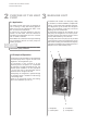
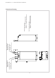
Heating water supply Heat pump outlet Heating water return Heat pump inlet Heat source return Heat pump inlet Heat source supply Heat pump outlet Heat source-side connections: .. 9/14CS 11/4“ internal/external thread .. 22/27CS 11/2" internal/external thread Heating-side connections: .. 9/14CS 1" internal/external thread .. 22/27CS 11/4“ internal/1" external thread APPENDIX: 11.
APPENDIX: 11.2 EQUIPMENT DATA Equipment Data EQUIPMENT DATA for water-to-water heat pumps for heating 1 TYPE AND COMMERCIAL DESCRIPTION 2 MODEL 2.1 Enclosure type acc. to EN 60 529 IP 20 IP 20 IP 20 IP20 2.2 Installation site indoor indoor indoor indoor 3 PERFORMANCE DATA 3.1 ..9CS ..14CS ..22CS ..27CS Operating temperature limits: Heating water supply °C max. 55 max. 55 max. 55 max. 55 Cold water (heat source) °C +7 to +25 +7 to +25 +7 to +25 +7 to +25 3.
APPENDIX: 11.3 PERFORMANCE CURVES/PRESSURE LOSSES 11.3.1 Performance Curves .. 9CS Wasseraustrittstemperatur in [°C] [°C] Water outlet temperature in Heating capacity in [kW] Heizleistung in [kW] 14 Bedingungen: Conditions: Heizwasserdurchsatz Heating water flow rate0,75 0.75 m³/h m3/h 3 Cold water flow rate 2.0 mm³/h /h Kaltwasserdurchsatz 2,0 12 35 50 10 8 6 4 2 0 Leistungszahl im Heizbetriebin(incl. Der anteiligen Coefficient of performance the heating mode Pumpenleistungen) (incl.
APPENDIX: 11.3 PERFORMANCE CURVES/PRESSURE LOSSES 11.3.2 Pressure Losses .. 9CS Pressure lossin in[Pa] [Pa] Druckverlust 20000 18000 Druckverluste Pressure Verdampfer losses evaporator at 10°C bei 10°C 16000 Pressure loss6,2 6.2kPa kPabei at Druckverlust cold water nominal flow rate2,0 2.
APPENDIX: 11.3 PERFORMANCE CURVES/PRESSURE LOSSES 11.3.3 Performance Curves .. 14CS Wasseraustrittstemperatur Water outlet temperature in [°C] Heating capacity in [kW] Heizleistung in [kW] 24 22 20 18 50 16 35 14 12 10 8 Bedingungen: Conditions: 3 Heizwasserdurchsatz 1,3mm³/h Heating water flow rate 1.3 /h 3 Cold water flow rate 3.33,3 m /h Kaltwasserdurchsatz m³/h 6 4 2 0 Coefficient of performance in the heating mode (incl. proportional pump energy) Leistungszahl im Heizbetrieb (incl.
APPENDIX: 11.3 PERFORMANCE CURVES/PRESSURE LOSSES 11.3.4 Pressure Losses .. 14CS Pressure lossinin[Pa] [Pa] Druckverlust 30000 Druckverluste Pressure losses Verdampfer bei1010°C evaporator at °C 25000 Pressure loss19 19kPa kPabei at Druckverlust cold water nominal flow rate 3,3 3.
APPENDIXG: 11.3 PERFORMANCE CURVES/PRESSURE LOSSES 11.3.5 Performance Curves .. 22CS Water outlet temperature in [°C] Wasseraustrittstemperatur Heating capacity in [kW] Heizleistung in [kW] 34 32 35 50 30 28 26 24 22 20 18 16 14 12 10 Bedingungen: Conditions: 3 Heizwasserdurchsatz 2,0mm³/h Heating water flow rate 2.0 /h 3 Cold water flow rate 5.0 m /h Kaltwasserdurchsatz 5,0 m³/h 8 6 4 2 0 Coefficient of performance in the heating mode (incl.
APPENDIX: 11.3 PERFORMANCE CURVES/PRESSURE LOSSES 11.3.6 Pressure Losses .. 22CS Pressure lossin in[Pa] [Pa] Druckverlust 35000 Druckverluste Pressure losses Verdampfer bei1010°C °C evaporator at 30000 Pressure loss20 20kPa kPa bei at Druckverlust 3 cold water nominal flow rate 5,0 5.
APPENDIX: 11.3 PERFORMANCE CURVES/PRESSURE LOSSES 11.3.7 Performance Curves .. 27CS Wasseraustrittstemperatur Water outlet temperature in [°C] Heating capacity in [kW] Heizleistung in [kW] 40 38 36 34 32 30 28 26 24 22 20 18 16 14 12 10 8 6 4 2 0 50 35 Bedingungen: Conditions: 3 Heizwasserdurchsatz 2,4mm³/h Heating water flow rate 2.4 /h Cold water flow rate 7.0 7,0 m3/hm³/h Kaltwasserdurchsatz Coefficient of performance in the heating mode (incl.
APPENDIX: 11.3 PERFORMANCE CURVES/PRESSURE LOSSES 11.3.8 Pressure Losses .. 27CS Pressure lossinin[Pa] [Pa] Druckverlust 50000 45000 Druckverluste Pressure losses evaporator at °C Verdampfer bei10 10°C 40000 Pressure loss16 16kPa kPabei at Druckverlust cold water nominal flow rate 7,0 7.
2A-51F 1A 11M 5K 1M >P 4F DN 2A 1A 1K DH DI 1 H3
F ssulfhcruD-.ötS CAV 0 59 69 51F 11M -.ötS 1M -.
V R U 3 M W S 2 1 (compressor supply via utility company disable contactor) (not in WI 9CS) 1M T 4 3 6 5 22K zH05 - CAV004 EP/3 zteN )ztühcsrrepS-UVE rebü rethcidreV gnusiepsniE( 3 )tkerid epmupnennurB gnusiepsniE( Mains power supply Wiring modification: In systems without utility company disable facility, the direct supply for the well pump may be dispensed with. /1X EP )SC9 IW ni thcin( 7N 6.
tr repseg PW = neffo tka tnoK 5R CAV42 2X 32K 22K RPS )L( 3F .l o p 2 1 rablhäw tsi EW net2 sed noitknuF eiD tr repseg PW = neffo tka tnoK 3B
APPENDIX: 11.4 WIRING DIAGRAMS 11.4.4 Legend .. 9CS TO .. 22CS A1 A2 Wire jumper, must be removed upon installation of a utility company disable contactor Wire jumper, must be removed if 2nd disable input is used B3* B4* Thermostat, hot water Thermostat, swimming pool water E9* E10* Electr. immersion heater, hot water Suppl. heat source (boiler or electr. heating element F2 F3 F4 F5 F10 F15 Load fuse for N1 relay outputs across J12 at J13 4.
2A 1A 11M 5K 1M 2A 1A >P 4F 51 81 61 1K DN 2A 1A DI DI DI DI 1 1 C 1 4 4 1 3 H 3 1.1K
F 1M 11 2M 11 41 1 2 1M-.ötS 1Q 2X 2A 1A CAV42 SVE RPS 11M-.ötS 41 ssulfhcruD-.
1M 2 5.1/- 1 8.1/ 41 5K 11M 4.1 / 21 11 A5,3-2,2 1Q 6 3 4 1 2 3 M 5 1 > I 2 > I 4 > I 3 6 5 EP 1X gnurefeilsuA ieb gnuthardreV EP 13L 12L 5X 3 A3,2 / A8PS mortsnneN / pyT-nepmuP sofdnurG :relletsreH zH05 - CAV004 EP/3 zteN )tkerid epmupnennurB gnusiepsniE( Manufacturer Pump type / Nominal current 2M 41F 1 2 R 21F U 3 M V S 4 3 11L 3 22K zteN zH05 - CAV004 EP/3 )ztühcsrrepS-UVE rebü rethcidreV gnusiepsniE( 3 25 5.1/ 1M 6 T W 7N 8.1/ 1.1K 5 .
4X 5R CAV42 2X 32K 22K RPS )L( 3F .l o p 2 1 rablhäw tsi EW net2 sed noitknuF eiD trrepseg PW = neffo tkatnoK 4B 3B
APPENDIX: 11.4 WIRING DIAGRAMS 11.4.8 Legend .. 27CS A1 A2 Wire jumper, must be removed upon installation of a utility company disable contactor Wire jumper, must be removed if 2nd disable input is used B1 B3* B4* Pressostat power adaptation for hot water preparation Thermostat, hot water Thermostat, swimming pool water E9* E10* Electr. immersion heater, hot water Suppl.
Shut-off valve with check valve Heat consumer Strainer Temperature sensor Flexible connecting hose Well circulating pump Heating circulating pump Hot water circulating pump External wall sensor Return sensor Hot water sensor Cold water Hot water Check valve Thermostat/manual valve Suction well Injection well Expansion vessel Circulating pump Safety valve Overflow valve Shut-off valve with drain Shut-off valve Ground water direction of flow Hot water tank Electric distribution Heat pump controll
APPENDIX: 11.6 EC DECLARATION OF CONFORMITY EC Declaration of conformity Declaration of Conformity The undersigned KKW Kulmbacher Klimageräte-Werk GmbH, Division Dimplex Am Goldenen Feld 18 D-95326 Kulmbach hereby confirm that the design and construction of the product(s) listed below, in the version(s) placed on the market by us, conform to the relevant basic requirements of the applicable EC directives.
Notes
Notes
KKW Kulmbacher Klimageräte-Werk GmbH Division Dimplex Am Goldenen Feld 18 D-95326 Kulmbach Subject to technical modifications Fax (0 92 21) 709-589 www.dimplex.