Instruction Manual
Manuals
Brands
Dimplex Manuals
Computer Accessories
Wall Switch Remote Control Kit WRCPF-KIT
11
12
13
14
15
16
17
18
19
20
12
www
.dimplex.com
W
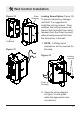
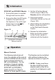
all Control Installation
Figure 15
Ensure each of the two
Controller lead wires are
connected to separate Low
V
oltage 24V~ only wires.
Low V
oltage
24V~ power source ONL
Y
Controller
wire leads
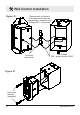
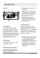
Figure 16
Flat Head
Screws
(supplied)
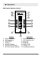
1
...
...
10
11
12
13
14
...
...
20