Owner’s Manual Model WRCPF-KIT IMPORTANT SAFETY INFORMATION: Always read this manual first before attempting to install or use this device. For your safety, always comply with all warnings and safety instructions contained in this manual to prevent personal injury or property damage. To view the full line of Dimplex products, please visit www.dimplex.
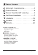
Table of Contents Welcome & Congratulations . . . . . . . . . . . . . 3 Product Overview. . . . . . . . . . . . . . . . . . . . . . 4 Receiver Installation (BF units only) . . . . . . . 5 Wall Control Installation . . . . . . . . . . . . . . . . 7 Initialization . . . . . . . . . . . . . . . . . . . . . . . . . 14 Operation. . . . . . . . . . . . . . . . . . . . . . . . . . . 15 Warranty . . . . . . . . . . . . . . . . . . . . . . . . . . .
Welcome & Congratulations Thank you and congratulations for choosing to purchase a Wall Switch Remote Control Kit from Dimplex, the world leader in electric fireplaces. Please carefully read and save these instructions. CAUTION: Read all instructions and warnings carefully before starting installation. Failure to follow these instructions may result in a possible electric shock, fire hazard and will void the warranty.
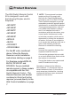
Product Overview ! The Wall Switch Remote Control Kit is designed to work with the following Dimplex electric fireplaces: • BF33STP • BF33DXP • BF39STP • BF39DXP • BF45DXP • BFSL33 • BLF50 • DF3033ST • DFG3033BLK 4 NOTE: This equipment has been tested and found to comply with the limits for Class B digital device, pursuant to part 15 of the FCC Rules. These limits are designed to provide reasonable protection against harmful interference in a residential installation.
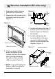
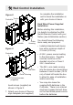
Receiver Installation (BF units only) 1. Open steel curtain (remove glass doors if applicable). 2. Remove two (2) screws on log grate and remove log grate (Figure 1). Figure 1 Figure 2 Log ember bed Back ledge Rear tab Side section Front edge 4. Locate and remove the two (2) screws on the manual control bracket (Figure 3). Remove the bracket. Screws Manual Controls 5. Locate and depress the mounting tabs on the plug connector and remove the manual control bracket from fireplace (Figure 3).
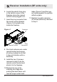
Receiver Installation (BF units only) 6. Locate the plastic 9-pin plug in the bottom corner of the fireplace where the manual controls were plugged in to. 7. Insert the plug connector from the remote control bracket (Figure 4) into plastic plug inside the fireplace. Figure 4 Remote Control ledge (Figure 2) and the logs are resting against the partially reflective glass. 11. Replace log grate using two (2) screws previously removed in step 2. Antenna Plug Connector 8.
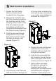
Wall Control Installation ! NOTE: All electrical wiring must comply with all national and local electrical codes and regulations. Always use a qualified and licensed electrician should you have any questions or concerns for all wiring work. ! NOTE: The Wall Switch Remote Control is made to fit standard Decora style faceplates. Due to material inconsistencies of individual faceplates, it may be necessary to remove the faceplate for operations such as changing batteries.
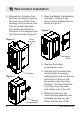
Wall Control Installation 2. Release the Controller from its Outer Housing by pushing the front face into the Outer Housing until you hear a click. This will release the pushlock latches and allow the Controller to be removed from the Outer Housing (Figure 5). Figure 5 3. Open the Battery Compartment as shown in Figure 6 and remove the Insulating Strip as shown in Figure 7. Figure 7 Outer Housing Insulating Strip 4. Replace the battery compartment cover. Controller Figure 6 Battery Compartment 8 5.
Wall Control Installation to complete the installation and to blend the installation in with your choice of decor. Figure 8 Controller Tracks Hard Wired Power Supplied Installation Before starting this installation, it is helpful to initialize the Wall Switch Remote Control with your firebox (see Initialization section). Guides Outer Housing You should have the following items ready and prepared: • Installed standard wall device box with a minimum depth of 2.5 inch (6.35 cm).
Wall Control Installation 1. Unpack the Wall Switch Remote Control and all hardware from its package. 2. Release the Controller from its Outer Housing by pushing the front face into the Outer Housing until you hear a click. This will release the pushlock latches and allow the Controller to be removed from the Outer Housing (Figure 5). of the two holes located on the wire lead storage compartment cover (make sure orientation is as shown as in Figure 11). Figure 11 3.
Wall Control Installation Figure 12 Controller Figure 13 Outer Housing Locking Screw Option (Figure 14) To prevent tampering, damage, and theft, it is suggested to install the locking screws. Once installed, the locking screws will prevent the Controller from being released from the Outer Housing without being removed first from the device box in the wall. ! NOTE: A Philips head screwdriver will be required for this step. Figure 14 Locking screws Outer Housing 8.
Wall Control Installation Figure 15 Ensure each of the two Controller lead wires are connected to separate Low Voltage 24V~ only wires. Controller wire leads Low Voltage 24V~ power source ONLY Figure 16 Flat Head Screws (supplied) 12 www.dimplex.
Wall Control Installation ! NOTE: Wire leads are not polarized due to the nature of this device. 9. Coil excess wiring to the back of the device box and insert the Controller and Outer Housing into the device box (Figure 16). Fasten with two supplied flat head screws. 10.Attach your choice of Decora style faceplate (not supplied) to complete the installation and to blend the installation in with your choice of decor. 11. Initialize the sender with the receiver installed in your fireplace.
Initialization After installation, locate the section which applies to your specific model of fireplace and follow the steps for remote control initialization and if required, re-initialization. Refer to your fireplace's owner's manual to locate manual or other controls as needed. BF Models Using the Included Receiver Module 1. Ensure that power is supplied through main service panel. 2. Inside the fireplace, locate the toggle switch on the manual controls and set to “Remote” (Figure 17-C).
Initialization DF3033ST and DFG3033 Models 1. Ensure that power is supplied through main service panel. 2. Ensure the Main On/Off Switch located in the switch box on the fireplace in the upper right On hand corner is in the position (Figure 19A). Figure 19 C B A 3. Set the 3 Position Manual Control (Figure 19B) to the Remote position (left position). 4. Press and hold the Initialization Button on the unit (Figure 19C). 5.
Operation Figure 20 A B C D A. On Button Pressing this button toggles sequentially through the three levels of the fireplace. Pressing once activates Level 1 - flame effect only, twice activates Level 2 - flame effect and Purifire™, three times activates Level 3 - flame effect, Purifire™ and heat. B. Off Button Pressing this button at any time will shut the unit off. • OFF (center): Makes the unit inoperable.
Operation Wall Switch Remote Control 6 7 5 1 2 8 9 10 11 12 13 4 1. 2. 3. 4. 5. 6. 7. Display Room Temperature Set Temperature Flame Effect Purifire™ Heat Off Indicator Function Lock Indicator RF Code Function Indicator 3 14 8. 9. 10. 11. 12. 13. 14.
Operation 1. Room Temperature Displays current ambient temperature in the room. 2. Set Temperature Displays and controls the heater to the temperature at which the thermostat is currently set to. Press 8 to lower the thermostat and press 9 to raise the thermostat. Pressing both 8 and 9 together will toggle between Celsius and Fahrenheit. 3. Flame Effect Icon The flame icon will flicker if and when the Flame Effect is turned on. Press 11 to turn the Flame Effect on, and press 10 to turn the Flame Effect off.
Operation 7. RF Code Function and Change Procedure In the event that the Wall Switch Remote Control does not work properly with the receiver due to interference from additional wireless signals, this function will allow the RF code to be changed. To enable this function, press 9 and 12 together. “COD” will appear on the display for five (5) seconds and the RF code will change automatically. Repeat procedure as needed to find a code that operates the fireplace without interference.
Warranty This Dimplex Wall Switch Remote Control is warranted against defects in workmanship and materials for two years from date of sale. This warranty does not apply to damage from accident, misuse, or alteration, nor where the connected voltage is more that 5 % above the nameplate voltage, nor to equipment improperly installed or wired or maintained in violation of the instruction sheet.