SUTP Mid Range Unvented Hot Water Heaters Installation Manual 30,50 & 75 Litres
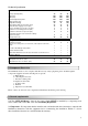
Important -This Manual Should Be Left With The Unit After Installation Table of Contents 1. Introduction.......................................................................................................................................2 2. Component Check List .....................................................................................................................3 3. General requirements .......................................................................................................
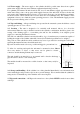
Technical Specification Model Number Storage capacity (litres) depth (mm) width (mm) Overall height incl t&p valve Height excl t&p valve Weight when full (kg) Cold feed/hot draw off connections (mm) Maximum water supply pressure (bar) System operating pressure (pre-set) (bar) Expansion vessel charge pressure (bar) Expansion relief valve set pressure (bar) Temperature and pressure relief valve settings: Lift pressure (bar) Lift temperature (ºC) SUTP30 SUTP50 SUTP75 30 400 400 665 586 47 22 12 3 3 6 50 4
3.3. Water supply – The water supply to the cylinder should be potable water direct from a public mains water supply with any water treatment equipment functioning correctly. For optimum performance the unit should be fed via a 15 mm diameter supply pipe direct from the mains water entry point to the property with supplies between 3bar and 12bar, however, the the unit can operate with a minimum supply pressure of 1.
4. Plumbing Installation 4.1. Connections. Connections MUST be made to the cylinder in accordance with Fig 1, and Fig 2. A drain cock (not supplied) should be fitted in the position shown in Fig 1 to facilitate draining of the cylinder. 4.2. Cold water supply – For best results, the cylinder should be fed by an uninterrupted 15mm supply pipe into the pressure reducing valve (PRV) with a supply pressure of between 3 and 12 bar maximum.
4.8 Connection arrangement for SUTP Mid Range Cylinder Fig 1 1 2 3 4 5 6 7 8 9 MAINS COLD WATER SUPPLY (15mm) STOP COCK (NOT SUPPLIED) PRESSURE REDUCING VALVE CHECK VALVE if supplied separately (included in RWC expansion relief valve) EXPANSION RELIEF VALVE - SET 6 BAR DISCHARGE PIPE 22mm DIA (SEE SECTION 7) DRAIN COCK (Not Supplied) TUNDISH EXPANSION VESSEL 4.9. Discharge arrangement. The Tundish must be installed in a position so that it is clearly visible by the user.
(b) Have a vertical section of pipe at least 300 mm long below the Tundish before any elbows or bends in the Pipework. (c) Be installed with a continuous fall (d) Have discharges visible at both Tundish and the final point of discharge, but where this is not possible or practically difficult, examples of acceptable discharge arrangements are: - Ideally below a fixed grating and above the water seal in a trapped gully - Downward discharge at low level, i.e.
Sizing of copper discharge pipe “D2” for common temperature relief valve outlet sizes Valve outlet Min size of size, diameter discharge pipe (inches) D1 in (mm) Min size of discharge pipe D2 from tundish in (mm) Max resistance allowed, expressed as a length of straight pipe, i.e. no elbows or bends. Resistance created by each elbow or bend (m) 22 up to 9 0.8 28 up to 18 1.0 35 up to 27 1.
4.10 Secondary Return Where required the hot water outlet to the taps may be returned to the cold water inlet of the cylinder using a circulating pump. The secondary return should be connected as per Figure 3. Note the 5litre vessel included with the water heater is suitable for pipe lengths of up to 180m. For longer pipe runs the cylinder should be increased in size accordingly. Figure 3 7. Electrical installation WARNING: THIS EQUIPMENT MUST BE EARTHED.
Fig 4 WARNING: THIS APPLIANCE MUST BE EARTHED. 8. Filling and commissioning8.1. Check that the expansion vessel charge pressure is 3 bar. 8.2. Check that all water and electric connections are tight and correctly configured. 8.3. Open the main stopcock and fill the unit. Open successive hot taps starting with the tap furthest from the heater. Leave each tap open for a few moments to allow all air and debris from the system to exit. Close all of the taps. 8.
9. Servicing and maintenance. 9.1. Servicing and maintenance must only be carried out by a competent unvented hot water installer or by Glen Dimplex UK Limited authorised personnel. 9.2. Before any work whatsoever is carried out on the installation, it MUST first be isolated from the mains electricity supply. 9.3 Only use spare parts authorised by Glen Dimplex UK Limited. The use of other parts will invalidate the warranty. 9.4.
10. Fault finding. Notice: Disconnect electrical supply before removing any electrical equipment cover. Fault Possible cause Remedy 1. Mains supply off 1. Open stopcock 2. Strainer in Pressure reducing valve blocked 2. Turn water supply off, remove strainer and clean. 3. Pressure reducing valve incorrectly fitted 1. Programmer if fitted is not switched on. 3. Re-fit correctly 2. High limit thermostat has tripped 3. Check and re-set Intermittent water discharge through tundish on warm-up 1.
11. Users instructions. 11.1 Your “SUTP Mid Range” unvented hot water cylinder has been designed to give many years of trouble free service and is made from hygienic high grade stainless steel. 11.2. When a hot tap is turned on there may be a short surge of water, this is quite normal with unvented systems and does not mean there is a fault. 11.4. When you first fill a basin the water may sometimes appear milky. This is due to very tiny air bubbles in the water which will clear very quickly. 11.5.
13. Installation, Commissioning and Service Record CUSTOMER DETAILS NAME ADDRESS TEL No. INSTALLER DETAILS COMPANY NAME ADDRESS DATE TEL No. REGISTRATION No. INSTALLER NAME COMMISSIONING ENGINEER (IF DIFFERENT) COMPANY NAME ADDRESS DATE TEL No. REGISTRATION No. INSTALLER NAME CYLINDER DETAILS MODEL CAPACITY LITRES SERIAL NO.