Sole/WasserWärmepumpe für Innenaufstellung Installation and Operating Instructions English Instructions d’installation et d’utilisation Français Montage- und Gebrauchsanweisung Brine-to-Water Heat Pump for Indoor Installation Bestell-Nr. / Order no. / No de commande : 452234.66.
Table of contents 1 Read immediately..........................................................................................................................E-2 1.1 Important Information.............................................................................................................................. E-2 1.2 Legal Provisions and Guidelines ............................................................................................................ E-2 1.3 Energy-Efficient Use of the Heat Pump ..
1 1 Read immediately 1.1 Important Information ATTENTION! Any work on the heat pump may only be performed by an authorised and qualified customer service. ATTENTION! The heat pump must not be tilted more than max. 45° (in either direction). English ATTENTION! 1.3 Energy-Efficient Use of the Heat Pump By operating this heat pump you contribute to the protection of our environment.
5 Baseline Unit 4 The baseline unit consists of a heat pump, ready for connection, for indoor installation, complete with sheet metal cabinet, control box and integrated controller. The refrigeration cycle contains the refrigerant R134a. Refrigerant R134a is CFC-free, non-ozone depleting and non-combustible. All components required for the operation of the heat pump are located in the control box.
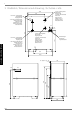
6 6 Installation 6.1 General Information As a rule, the unit must be installed indoors on a level, smooth and horizontal surface. The entire base frame should make full contact with the surface in order to ensure adequate sound insulation. Failing this, additional sound insulation measures may become necessary. English The heat pump should be installed to allow easy maintenance/ service access. This is ensured if a clearance of approx. 1 m in front of the heat pump is maintained.
8.3 An automatic circuit-breaker with simultaneous tripping of all external conductors is to be provided in the load power supply. The circuit-breaker must be an all-pole disconnect device with a contact gap of at least 3 mm. The same applies to any additional disable contactors that may be required, e.g. during shut-off periods imposed by the utility company.
9 9 Care/Cleaning 9.1 Care The heat pump is maintenance-free. To prevent malfunctions due to sediments in the heat exchangers, care must be taken that no im-purities can enter the heat source system and the heating installation. In the event that operating malfunctions due to contamination occur nevertheless, the system should be cleaned as described below. English 9.
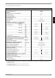
12 12 Equipment Data Device information for brine-to-water heat pumps (heating only) 1 Type and order code 2 Design 2.1 Degree of protection according to EN 60 529 2.2 Installation location Performance data 3.1 Operating temperature limits: IP 21 Indoors Heating water flow °C Brine (heat source) °C up to 70 -5 to +25 Antifreeze Monoethylene glycol Minimum brine concentration (-13 °C freezing temperature) 3.2 3.
Anhang / Appendix / Annexes 1 Maßbild / Dimensioned drawing / Schéma coté ........................................................................ A-II 2 Diagramme / Schematics / Diagrammes ................................................................................... A-III 3 Stromlaufpläne / Wiring diagrams / Schémas électriques ...................................................... A-IV 3.1 3.2 3.3 3.4 4 Steuerung / Control / Commande ...........................................................
1 1 Maßbild / Dimensioned drawing / Schéma coté ´ ,QQHQ $XHQJHZLQGH :lUPHTXHOOH (LQJDQJ LQ :3 ´ LQWHUQDO H[WHUQDO WKUHDG +HDW VRXUFH +HDW SXPS LQOHW ,QQHQ $XHQJHZLQGH +HL]XQJVYRUODXI $XVJDQJ DXV :3 )LOHWDJH LQW H[W ´ 6RXUFH GH FKDOHXU (QWUpH GDQV OD 3$& ´ LQWHUQDO H[WHUQDO WKUHDG +HDWLQJ ZDWHU VXSSO\ +HDW SXPS RXWOHW )LOHWDJH LQW H[W ´ $OOHU HDX GH FKDXIIDJH 6RUWLH GH OD 3$& ´ LQWHUQDO H[WHUQDO WKUHDG +HDWLQJ ZDWHU UHWXUQ +HD
2 2 Diagramme / Schematics / Diagrammes +HL]OHLVWXQJ LQ >N:@ +HDWLQJ FDSDFLW\ LQ >N:@ 3XLVVDQFH GH FKDXIIDJH HQ >N:@ :DVVHUDXVWULWWVWHPSHUDWXU LQ >&@ :DWHU RXWOHW WHPSHUDWXUH LQ >&@ 7HPSpUDWXUH GH VRUWLH GH O HDX HQ >&@ 9HUGLFKWHU %HWULHE FRPSUHVVRU PRGH )RQFWLRQQHPHQW j FRPSUHVVHXUV 9HUGLFKWHU %HWULHE FRPSUHVVRU PRGH )RQFWLRQQHPHQW j FRPSUHVVHXU %HGLQJXQJHQ Â &RQGLWLRQV Â &RQGLWLRQV 6ROHGXUFKVDW] %ULQH IORZ UDWH 'pELW G HDX JO\FROpH P K Anhang · Appendix · Annexes +HL]ZDVVHU
3 3 Stromlaufpläne / Wiring diagrams / Schémas électriques 3.
1HW] Â 0DLQV Â 5pVHDX Anhang · Appendix · Annexes 0 LVW RSWLRQDO 0 LV RSWLRQDO 0 HQ RSWLRQ 3.2 3.2 Last / Load / Charge www.dimplex.
3.3 3.
3.4 Legende / Legend / Légende A1 Drahtbrücke von J5-ID3>X2, muss eingelegt werden, wenn kein EVU-Sperrschütz gebraucht wird Kontakt offen = EVU-Sperre Wire jumper across J5-ID3>X2 must be inserted if no utility company disable contactor is used Contact open - utility block (EVU) A2 Drahtbrücke, muss bei Verwendung des 2.
4 4 Hydraulisches Prinzipschema / Hydraulic block diagrams / Schéma hydraulique 4.
4.2 4.
5 5 Konformitätserklärung / Declaration of Conformity / Déclaration de conformité Anhang · Appendix · Annexes A-X
Glen Dimplex Deutschland GmbH Geschäftsbereich Dimplex Am Goldenen Feld 18 D-95326 Kulmbach Irrtümer und Änderungen vorbehalten. Subject to alterations and errors. Sous réserve d’erreurs et modifications. +49 (0) 9221 709 565 www.dimplex.