Service Manual Model RBF30 RBF36 RBF36P RBF42 Part Number 6909780100 6909790100 6909790200 6909800100 IMPORTANT SAFETY INFORMATION: Always read this manual first before attempting to service this firebox. For your safety, always comply with all warnings and safety instructions contained in this manual to prevent personal injury or property damage. Dimplex North America Limited 1367 Industrial Road Cambridge ON Canada N3H 4W3 1-888-346-7539 www.dimplex.
TABLE OF CONTENTS Operation. . . . . . . . . . . . . . . . . . . . . . . . . . . . . . . . . . . . . . . . . . . . . . . . . . . . . . . . . . . 3 Maintenance. . . . . . . . . . . . . . . . . . . . . . . . . . . . . . . . . . . . . . . . . . . . . . . . . . . . . . . . . 5 Exploded Parts Diagram. . . . . . . . . . . . . . . . . . . . . . . . . . . . . . . . . . .
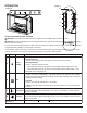
OPERATION Figure 3 Figure 1 A H B C D F I E G J Touch Panel and Remote Controls WARNING: The RevillusionTM Built-in Electric Firebox must be installed properly before it is used. CAUTION: Except for installation and cleaning described in this manual, an authorized service representative should perform any other servicing. The manual controls for the RevillusionTM Built-in Electric Firebox are located on the front panel. Touch an icon to activate.
Icon Function Description Heat Enable Hold both Heat ( on the screen. Heat Disable Hold both Heat ( ) and Temp– ( ), on the unit, for 2 seconds, when temperature is adjusted "---" displays on the screen. E F Color Themes 360o Light G Brightness H Flame ) and Temp– ( ), on the unit, for 2 seconds. Temperature displays Press multiple times to change the flame base colors from Red to Blue to Off.
MAINTENANCE General Maintenance Inspect the built-in electric firebox regularly, depending upon conditions, and at a minimum yearly intervals. Remove dust and clean the logs, grate, and base as required. WARNING: Disconnect power and allow heater to cool before attempting any maintenance or cleaning to reduce the risk of fire, electric shock, or injury. CAUTION: Except for installation and cleaning described in this manual, an authorized service representative should perform any other servicing.
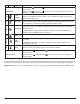
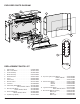
EXPLODED PARTS DIAGRAM 6 4 17 5 2 1 14 13 9 3 10 7 15 11 12 16 8 REPLACEMENT PARTS LIST 1. Power Supply . . . . . . . . . . . . . . . . . . . . . . . . . 2100250100RP 2. Main Control Board . . . . . . . . . . . . . . . . . . . . 3001810101RP 3. Control Assembly . . . . . . . . . . . . . . . . . . . . . . 3001830100RP 4. Blower Assembly . . . . . . . . . . . . . . . . . . . . . . . 5300110500RP 5. Heater Elements. . . . . . . . . . . . . . . . . . . . . . . 2200510700RP 6. Cutout. . .
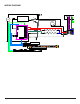
WIRING DIAGRAM M M 7
LOG SET ASSEMBLY REPLACEMENT FLAME SCREEN REPLACEMENT WARNING: If the firebox was operating prior to servicing, allow at least 10 minutes for the heating elements to cool off to avoid accidental burning of skin. WARNING: If the firebox was operating prior to servicing, allow at least 10 minutes for the heating elements to cool off to avoid accidental burning of skin. WARNING: Disconnect power before attempting any maintenance to reduce the risk of electric shock or damage to persons. 1.
EMBER LED LIGHT REPLACEMENT Tools Required: Philips head screwdriver Needle-nose pliers WARNING: If the firebox was operating prior to servicing, allow at least 10 minutes for the heating elements to cool off to avoid accidental burning of skin. WARNING: Disconnect power before attempting any maintenance to reduce the risk of electric shock or damage to persons. 1. Remove the front glass or any accessories that are around the fireplace and will inhibit your ability to fully access the unit. 2.
8. 9. 10. 11. 12. either end. Lift the back log assembly out of the unit. Locate the flame base LED assembly and squeeze the mounting tabs located along the board with the needlenose pliers, to release the tabs and lift off. DIsconnect the light strip by pulling the connector out of the assembly on the left hand side. Connect the new light strip. Re-assemble the unit in reverse order from the instructions above.
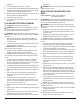
Figure 4 Cutout Element Blower Assembly Main Control Board Power Supply Thermistor Main Control Assembly WARNING: Ensure wires do not come in contact with moving parts by securing wires in wiring tie wraps. POWER SUPPLY REPLACEMENT Tools Required: Philips head screwdriver Flat Head Screwdriver WARNING: If the firebox was operating prior to servicing, allow at least 10 minutes for the heating elements to cool off to avoid accidental burning of skin.
to persons. 1. Remove the front glass or any accessories that are around the fireplace and will inhibit your ability to fully access the unit. 2. Slide the log set assembly forward and lift the log set assembly and the ember mat out. (Figure 3) ! NOTE: The log set assembly has a wire attached to the unit which can be temporarily disconnected for easier access. 3. On either side of the firebox gently remove the brick panels by placing you finger in the gap and pulling forward.
12. Re-assemble the remainder of the firebox in reverse order from the instructions above. WARNING: Ensure wires do not come in contact with moving parts by securing wires in wiring tie wraps. 14. Re-assemble the remainder of the firebox in reverse order from the instructions above. CUTOUT REPLACEMENT MAIN CONTROL ASSEMBLY REPLACEMENT Tools Required: Philips head screwdriver Flat Head Screwdriver WARNING: Ensure wires do not come in contact with moving parts by securing wires in wiring tie wraps.
THERMISTOR REPLACEMENT Tools Required: Philips head screwdriver Flat Head Screwdriver WARNING: If the firebox was operating prior to servicing, allow at least 10 minutes for the heating elements to cool off to avoid accidental burning of skin. WARNING: Disconnect power before attempting any maintenance to reduce the risk of electric shock or damage to persons. 1. Remove the front glass or any accessories that are around the fireplace and will inhibit your ability to fully access the unit. 2.
TROUBLESHOOTING GUIDE PROBLEM CAUSE SOLUTION General Circuit breaker trips or fuse blows when unit is turned on Short in unit wiring. Trace wiring in unit. Improper circuit current rating Additional appliances may exceed the current rating of the circuit breaker or fuse. Plug unit into another outlet or install unit on a dedicated 15 amp circuit.
PROBLEM CAUSE SOLUTION Heater Heater is not turning Off Heater is not turning On Heater is turning off after a couple of minutes of operation Heater emits an odor Heater fan turns on but heater lacks heat Heating element is glowing red Heater fan runs continuously Improper operation Refer to Operation Section Defective main control board Replace main control board.