
Firebox Service Manual

11
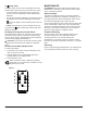
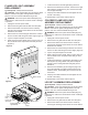
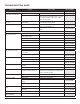
Side Section
Front
Edge
Log
Ember
Bed
Back
Ledge
Rear
Tab
Figure 7
brackets to the mantel.
4. Remove the front glass and set aside in a safe place.
5. Pull the front edge of the plastic Ember Bed or plastic
grate up and forward until the rear tab releases from
the ledge located at the bottom of the Partially Reect-
ive Panel. (Figure 7)
!
IMPORTANT: Only handle the Log Set by the Ember
Bed.
!
NOTE: Log Set ts tightly into rebox, some force may
be necessary to remove.
6. Reassemble in the reverse order as above.
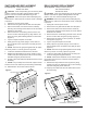
PARTIALLY REFLECTIVE PANEL
REPLACEMENT
Tools Required: Phillips Head Screwdriver
CAUTION: If unit was operating prior to servicing allow
at least 10 minutes for lights, heating elements and top
panel to cool off to avoid accidental burning of skin.
WARNING: Disconnect power before attempting any
maintenance to reduce the risk of electric shock or damage
to persons.
1. Unplug the unit from power outlet.
2. Remove the front glass and set aside in a safe place.
3. Remove the rebox from the back of the mantel by
removing the retaining screws which secure the rebox
brackets to the mantel.
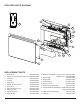
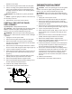
4. Remove the two screws along the back of the unit and
the two on either side along the bottom edge. (Figure 5)
5. Lay the Compact Fireplace on its back.
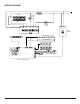
6. Gently open the bottom panel, laying it on the work sur-
face so that all of the components can easily be seen.
(Figure 6)
7. Remove the two screws on each side that secure the
partially reective support bracket to the rebox.
8. Remove the partially reective support bracket.
9. Remove the partially reective panel by sliding it out of
the side channels towards the bottom.
10. Install the new partially reective panel.
11. Reassemble in the reverse order as above.
THERMISTOR REPLACEMENT
Tools Required: Phillips Head Screwdriver
CAUTION: If unit was operating prior to servicing allow
at least 10 minutes for lights, heating elements and top
panel to cool off to avoid accidental burning of skin.
WARNING: Disconnect power before attempting any
maintenance to reduce the risk of electric shock or damage
to persons.
1. Unplug the unit from power outlet.
2. Remove the front glass and set aside in a safe place.
3. Remove the rebox from the back of the mantel by
removing the retaining screws which secure the rebox
brackets to the mantel.
4. Remove the two screws along the back of the unit and
the two on either side along the bottom edge. (Figure 5)
5. Lay the Compact Fireplace on its back.
6. Gently open the bottom panel, laying it on the work sur-
face so that all of the components can easily be seen.
(Figure 6)
7. Remove the two screws on each side that secure the
partially reective support bracket to the rebox.
8. Remove the partially reective support bracket.
9. Remove the partially reective panel by sliding it out of
the side channels towards the bottom.
10. Locate and release the thermistor from the back panel
by using needle nose pliers to depress the tab on the
mounting standoffs and gently lift the board off.
11. There is one connection located on the display/control
board that may require the board to be removed. This
can be done by removing the two screws on the right
hand side of the unit to remove the display/control
board to remove the connection and replace it with the
new one.
12. Install the new thermistor.
13. Reassemble in the reverse order as above.