
Firebox Service Manual

15
GWAVE
TM
ASSEMBLY
REPLACEMENT
Tools Required: Phillips Head Screwdriver
Flat Head Screwdriver
CAUTION: If unit was operating prior to servicing allow
at least 10 minutes for heating elements and top panel to
cool off to avoid accidental burning of skin.
WARNING: Disconnect power before attempting any
maintenance to reduce the risk of electric shock or damage
to persons.
MOD 0-A
1. Unplug the unit from power outlet.
2. Remove the rebox from the front of the mantel and
remove front glass assembly (glass lifts off).
CAUTION: Even though the glass is safety glass it
may break if bumped, struck of dropped. Care must be
taken when handling the glass.
3. Remove the loose media from the unit (if applicable).
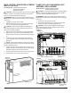
4. To loosen the back panel to allow removal of the top
pane, remove the 4 screws along the top of the back
panel and the rst screw along either side of the back
of the unit.
5. Remove the 12 screws around the top panel of the re-
box and the 2 along the middle of the panel (Figure 3).
6. Remove the front portion of the panel, as well, by re-
moving the 5 screws along the top.
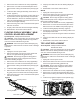
7. Locate the gWave
TM
assembly (Figure 4).
8. Release the gWave
TM
assembly from the top panel by
gently depressing the tab on the top of the assembly
with the at head screwdriver and gently remove.
9. Properly orient and connect the new assembly.
10. Reassemble in the reverse order as above.
MOD B
1. Unplug the unit from power outlet.
2. Remove the rebox from the front of the mantel and
remove front glass assembly (glass lifts off).
CAUTION: Even though the glass is safety glass it
may break if bumped, struck of dropped. Care must be
taken when handling the glass.
3. Remove the loose media from the unit (if applicable).
4. Remove the 14 screws around the back panel of the
rebox and the 3 along the middle of the panel (Figure
3).
5. Locate and remove the two screws, recessed in the
top assembly, this will allow you to gently push the
gWave
TM
assembly out the front of the unit, through the
opening in the back.
6. Disconnect the old assembly and connect the new as-
sembly.
7. Slide the assembly back into the unit.
8. Reassemble in the reverse order as above.
RELAY BOARD REPLACEMENT
(Mod B units Only)
Tools Required: Phillips Head Screwdriver
CAUTION: If unit was operating prior to servicing allow
at least 10 minutes for heating elements and top panel to
cool off to avoid accidental burning of skin.
WARNING: Disconnect power before attempting any
maintenance to reduce the risk of electric shock or damage
to persons.
1. Unplug the unit from power outlet.
2. Remove the rebox from the front of the mantel and
remove front glass assembly (glass lifts off).
CAUTION: Even though the glass is safety glass it
may break if bumped, struck of dropped. Care must be
taken when handling the glass.
3. Remove the loose media from the unit (if applicable).
4. Remove the 14 screws around the back panel of the
rebox and one in the middle of the panel (Figure 3).
5. Locate the relay board assembly. (Figure 4)
6. Transfer the connections from the existing board to the
new display/control board.
7. Remove the 4 screws securing the board to the assem-
bly.
8. Properly orient and insert the new oating display as-
sembly.
9. Reassemble in the reverse order as above.
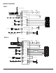
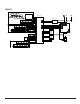
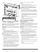
Figure 7
Log set
Electronics Junction Board
Lower Light
Assembly
Mirror Bracket