
Firebox Service Manual

7
SWITCHBOARD REPLACEMENT
Tools Required: Phillips Head Screwdriver
Needle Nose Pliers
CAUTION: If unit was operating prior to servicing allow
at least 10 minutes for lights, heating elements and top
panel to cool off to avoid accidental burning of skin.
WARNING: Disconnect power before attempting any
maintenance to reduce the risk of electric shock or damage
to persons.
1. Unplug the unit from power outlet.
2. Remove the front glass and set aside in a safe place.
3. Remove the rebox from the back of the mantel by
removing the retaining screws which secure the rebox
brackets to the mantel.
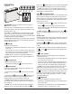
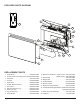
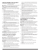
4. Remove the three screws along the back of the unit,
the two on either side along the top edge and the one
at the top of the glass retaining bracket on both sides.
(Figure 3)
5. Lay the Compact Fireplace on its back.
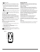
6. Gently open the top panel, laying it on the work sur-
face so that all of the components can easily be seen.
(Figure 4)
!
NOTE: The wires are grouped together with tie wraps,
which may need to cut to fully open the top panel.
7. Locate the switchboard and disconnect the wire.
8. Release the switchboard from the top panel by using
needle nose pliers to depress the tab on the mounting
standoffs and gently lift the board off.
9. Properly orient and install the switchboard and connect
the wiring.
!
NOTE: If any tie wraps were removed, replace and en-
sure that none of the wires are pinched during reassembly.
10. Reassemble in the reverse order as above.
Figure 3
RELAY BOARD REPLACEMENT
Tools Required: Phillips Head Screwdriver
Flat Head Screwdriver
Needle Nose Pliers
CAUTION: If unit was operating prior to servicing allow
at least 10 minutes for lights, heating elements and top
panel to cool off to avoid accidental burning of skin.
WARNING: Disconnect power before attempting any
maintenance to reduce the risk of electric shock or damage
to persons.
1. Unplug the unit from power outlet.
2. Remove the front glass and set aside in a safe place.
3. Remove the rebox from the back of the mantel by
removing the retaining screws which secure the rebox
brackets to the mantel.
4. Remove the three screws along the back of the unit and
the two on either side along the top edge. (Figure 3)
5. Remove the six screws on the top surface, to release
the top panel. (Figure 3)
6. Lay the Compact Fireplace on its back.
7. Gently open the top panel, laying it on the work sur-
face so that all of the components can easily be seen.
(Figure 4)
!
NOTE: The wires are grouped together with tie wraps,
which may need to cut to fully open the top panel.
8. Locate the relay board and disconnect the wiring con-
nections noting their original locations.
!
NOTE: A at head screwdriver can be used to gently
pry between the end of the connector and the switch to
release the wires.
9. Release the relay board from the top panel by using
needle nose pliers to depress the tab on the mounting
standoffs and gently lift the board off.
10. Properly orient and insert the new board and connect
all of the wiring.
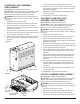
Top Panel Screws
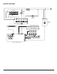
Figure 4
Switchboard
Power
Supply
Relay
Board
Heater
Assembly
Power Cord
Display/Control Board
Securing Screws