
Installation Sheet

www.dimplex.com2
recommended for recessed installation of these heaters while
two conductor, metallic sheath cable (BX) is recommended for
surface installations. Use number 12 gauge wire for all models.
Each heater should be on an individual, properly fused circuit.
WARNING: Wiring procedures and connections should be
in accordance with the National Electric code (NEC) and local
codes.
1. When installing optional wall thermostat, unit mounted ther-
mostat must be set at it’s highest setting.
2. All external control equipment (shown with dashed lines) fur-
nished by customer. Control wiring must be suitable for 600V.
3. Heater branch circuits shall have a carrying capacity of no
less than 125% of maximum load served.
Operation
WARNING: This heater must be properly installed before it is
used.
These heaters are operated by an on/off switch and also a temperature
control with a knob.
1. Turn the switch ON. Remember there is a fan delay.
2. Set thermostat by turning the knob to desired room comfort level
(clockwise to increase heat output). Once you have determined
the proper setting to provide the heat level you prefer, you need
not touch the knob again.
3. Turn the switch OFF to turn off heater. To reuse, simply turn the
switch ON - the temperature level you wish has been previously set.
!
NOTE: This heater is equipped with a fan delay switch which
delays the fan operation until the heating grid has heated sufciently
to assure the circulation of only warm air. This same switch permits the
fan to operate after power to the grid has been shut off by thermostat
action, thus utilizing all the heat remaining in the grid.
When the heater is shut down by turning the switch OFF, power to
both fan motor and element is diconnected and the fan motor will not
continue to operate.
WARNING: Should the OVERTEMP light come on, disconnect
power to the heater, turn the switch OFF or turn down the thermostat
fully counterclockwise and call a licenced electrician. DO NOT USE
HEATER UNTIL PROBLEM IS DETERMINED AND FIXED.
Tamper Proof Models
The ON/OFF switch and the temperature regulating thermostat are
recessed so that the continuous grille front panel can be installed
concealing both controls. The thermostat is operated by removing
the front panel. The ON/OFF switch can be operated by inserting a
slender non metallic rod between grille louvers and turning the switch
ON or OFF.
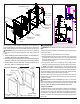
Figure 3
HEATER WALL BOX
SHEET METAL
SCREW
GROUNDING
SCREW
REMOVE THIS
KNOCKOUT
SERVICE CABLE
25” SERVICE
LEADS
Figure 2: Surface
SURFACE
WALL BOX
Figure 1: RECESSED
FRAME
HEATER
ASSEMBLY
GRILL
THERMOSTAT
KNOB
WALL BOX
OVERTEMP LIGHT
120/208/240V
GROUNDING SCREW
3 1/4”MINIMUM
PHILLIPS HEAD
SCREW
REMOVE THIS
KNOCKOUT
WALL OPENING
18 1/4”
WALL OPENING
14 1/4”
12” CABLE