
Service manual
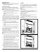


5
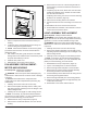
EXPLODED PARTS DIAGRAM
6
2
3
4
5
9
10
7
12
1
REPLACEMENT PARTS
1. Remote Control ...................9600385600RP
2. Remote Control Receiver ...........9600580300RP
3. White Rock Media. . . . . . . . . . . . . . . . .9600650100RP
4. Black Rock Media . . . . . . . . . . . . . . . . .6909500100RP
5. Media Tray ......................9600660100RP
6. Heating Assembly (with cutout) .......9600680100RP
7. Light Holder Assembly .............9600610100RP
8. Removable Rell Container with Cap 0441440100RP
9. Cap for Rell Container. . . . . . . . . . . . .0441440300RP
10. Top Cover Assembly ...............9600670100RP
11. Water Reservoir (Sump) ...........0441380100RP
12. Fan Assembly . . . . . . . . . . . . . . . . . . . .5300300100RP
13. Fan Housing Assembly . . . . . . . . . . . . .9600540100RP
14. Fan Filter. . . . . . . . . . . . . . . . . . . . . . . .8600300100RP
15. Transducer ......................3800040100RP
16. Power Cord
Mod 0-A ........................9600385500RP
Mod B . . . . . . . . . . . . . . . . . . . . . . . . . .9600740100RP
17. On/Off Switch ....................9600383500RP
18. 3-Position Switch .................9600383600RP
19. Transformers. . . . . . . . . . . . . . . . . . . . .9600690100RP
20. Mounting Hardware Kit . . . . . . . . . . . . .9600700100RP
21. Potentiometer ....................9600640100RP
22. Thermostat Assembly . . . . . . . . . . . . . .9600620100RP
23. Control Knob . . . . . . . . . . . . . . . . . . . . .9600630100RP
24. Power Board . . . . . . . . . . . . . . . . . . . . .9600590100RP
25. IR Receiver with Lens . . . . . . . . . . . . . .9600600100RP
26. Light Bulbs ............................ RB400
13
11
14
23
20
17
16
21
18
22
15
24
25