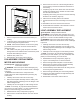
Service Manual Model Number: DWOP20R DWOP20BR UL Part Number 6909030100 IMPORTANT SAFETY INFORMATION: Always read this manual first before attempting to service this fireplace. For your safety, always comply with all warnings and safety instructions contained in this manual to prevent personal injury or property damage. Dimplex North America Limited 1367 Industrial Road Cambridge ON Canada N1R 7G8 1-888-346-7539 www.dimplex.
TABLE OF CONTENTS OPERATION. . . . . . . . . . . . . . . . . . . . . . . . . . . . . . . . . . . . . . . . . . . . . . . . . . . . . . . . . 3 MAINTENANCE . . . . . . . . . . . . . . . . . . . . . . . . . . . . . . . . . . . . . . . . . . . . . . . . . . . . . . 4 EXPLODED PARTS DIAGRAM. . . . . . . . . . . . . . . . . . . . . . . . . . . . . . . . . . . . . . .
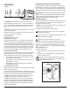
OPERATION Resetting the Temperature Cutoff Switch Should the heater overheat, an automatic cut out will turn the fireplace off and it will not come back on without being reset. It can be reset by switching the On/ Off Switch to Off and waiting ten (10) minutes before switching the unit back on. CAUTION: If you need to continuously reset the heater, unplug the unit and call Dimplex North America Limited at 1-888-346-7539 for technical support. Please have your model and serial number ready when calling.
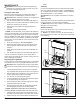
MAINTENANCE W ARNING: Disconnect power before attempting any maintenance or cleaning to reduce the risk of fire, electric shock or damage to persons. Filling the water tank When the water tank is empty, the flame effect shuts off and you will hear 2 audible beeps, follow these steps. CAUTION: Allow at least five minutes for components to cool before disassembling the unit to refill. 1. Turn the On/Off switch to the off position (0) (Figure 1) 2.
EXPLODED PARTS DIAGRAM 1 18 5 25 24 11 6 12 14 3 13 10 9 23 2 15 22 21 16 4 7 17 20 REPLACEMENT PARTS 1. 2. 3. 4. 5. 6. 7. 8. 9. 10. 11. 12. 13. 14. Remote Control. . . . . . . . . . . . . . . . . . . 9600385600RP Remote Control Receiver. . . . . . . . . . . 9600580300RP White Rock Media. . . . . . . . . . . . . . . . .9600650100RP Black Rock Media . . . . . . . . . . . . . . . . .6909500100RP Media Tray . . . . . . . . . . . . . . . . . . . . . . 9600660100RP Heating Assembly (with cutout).
WIRING DIAGRAM 6 www.dimplex.
HEATER ASSEMBLY REPLACEMENT Tools Required: Philips head screwdriver Flat head screwdriver WARNING: If the fireplace was operating prior to servicing, allow at least 10 minutes for light bulbs and heating elements to cool off to avoid accidental burning of skin. WARNING: Disconnect power before attempting any maintenance to reduce the risk of electric shock or damage to persons. 1. Carefully remove the rocks from the front tray. 2.
Figure 7 4. Properly orient and insert the new switch and connect all of the wiring. 5. Reassemble in the reverse order as above. THERMOSTAT REPLACEMENT 1. Follow “Component Access” instructions before proceeding. 2. Locate the On/Off switch and disconnect the wiring connections noting their original locations. (Figure 8) ! NOTE: A flat head screwdriver can be used to gently pry between the end of the connector and the switch to release the wires. 3.
Figure 8 Heater Assembly IR Sensor Transformer Remote Receiver Power Board Thermostat On/Off Switch 3 Position Switch Potentiometer elements to cool off to avoid accidental burning of skin. WARNING: Disconnect power before attempting any maintenance to reduce the risk of electric shock or damage to persons. 1. Follow “Component Access” instructions before proceeding. 2. Locate the remote control receiver and disconnect the wiring connections noting their original locations.
Figure 9 6. Remove the fan motor out of the housing and disconnect the wiring connection located near the bottom of the housing. 7. If replacing only the motor, attach new motor and reassemble the remainder of the cassette in reverse order from the instructions above. • If replacing the housing, remove the 3 screws attaching the base to the cassette. (Figure 6) 8. Attach new fan housing base to the cassette. 9. Transfer the filter from the old housing to the new housing. 10.
TROUBLESHOOTING GUIDE PROBLEM CAUSE SOLUTION General Circuit breaker trips or fuse blows when unit is turned on Short in unit wiring. Trace wiring in unit. Improper circuit current rating Additional appliances may exceed the current rating of the circuit breaker or fuse. Plug unit into another outlet or install unit on a dedicated 15 amp circuit.
PROBLEM CAUSE SOLUTION Heater Heater is not turning off Heater is not turning on Heater is turning off after a couple of minutes of operation Heater emits an odor Heater fan turns on but heater lacks heat Heating element is glowing red Heater fan runs continuously Improper operation Refer to Operation Section Defective 3 position switch Replace 3 position switch Defective thermostat Replace thermostat Improper operation Refer to Operation Section Loose wiring Trace Wiring Defective heater