
& DWF5252B Service Manual


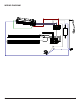


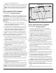

Table Of Contents
- Operation
- Maintenance
- Exploded Parts Diagram
- Replacement Parts List
- Wiring Diagram
- Partially Reflective Glass Replacement
- Switchboard Replacement
- Display/Control Board Replacement
- Power Cord Replacement
- Relay Board Replacement
- AC/DC Adapter Replacement
- Heater Assembly Replacement
- Flicker Rod Replacement
- Flicker Motor Replacement
- LED Light Strip Replacement
- Troubleshooting Guide

7
7. Remove the end panel being
careful not to add any strain
to the wires connecting to the
switchboard.
8. Gently guide the partially reec-
tive glass out the open side of
the rebox and replace with new
piece.
9. Re-assemble the remainder of
the replace in reverse order from
the instructions above.
!
NOTE: Be sure that the anges
on the end panel are positioned on
the interior of the outside panel of
the replace.
SWITCHBOARD REPLACEMENT
Tools Required: Phillips head screwdriver
Small adjustable wrench
WARNING: If the replace was operating prior to ser-
vicing, allow at least 10 minutes for light bulbs and heating
elements to cool off to avoid accidental burning of skin.
WARNING: Disconnect power before attempting any
maintenance to reduce the risk of electric shock or damage
to persons.
1. On either side of the rebox, remove the retaining
screws and carefully remove the glass assembly from
the rest of the assembly. (Figure 3)
2. Carefully remove the acrylic media from the front tray.
3. If applicable, remove the replace assembly from the
wall by carefully lifting it upward, releasing it from the
anges of the wall-mounting bracket. (Figure 4).
4. Carefully set the unit upright on a at working surface.
!
NOTE: If necessary, lay a protective barrier between
the unit and your work surface, (i.e. cloth, cardboard, thick
plastic) to avoid scratching your work surface.
5. On the right end, with the switchboard, remove the ten
screws around the outside of the end panel. (Figure 5)
6. Lay unit on its back and remove the remaining 9 screws
from the end panel.
7. Remove the end panel being careful not to add any
strain to the wires connecting to the switchboard. (Fig-
ure 6)
8. Gently guide the partially reective glass out the open
side of the rebox.
9. Follow the switchboard wiring to the display/control
board and replace the old connection with the new con-
nection.
10. Locate and remove the defective switchboard.
11. Install the new switchboard.
12. Re-assemble the remainder of the replace in reverse
order from the instructions above.
PARTIALLY REFLECTIVE GLASS
REPLACEMENT
Tools Required: Phillips head screwdriver
WARNING: If the replace was operating prior to ser-
vicing, allow at least 10 minutes for light bulbs and heating
elements to cool off to avoid accidental burning of skin.
WARNING: Disconnect power before attempting any
maintenance to reduce the risk of electric shock or damage
to persons.
1. On either side of the rebox, remove the retaining
screws and carefully remove the glass assembly from
the rest of the assembly. (Figure 3)
2. Carefully remove the acrylic media from the front tray.
3. If applicable, remove the replace assembly from the
wall by carefully lifting it upward, releasing it from the
anges of the wall-mounting bracket. (Figure 4).
4. Carefully set the unit upright on a at working surface.
!
NOTE: If necessary, lay a protective barrier between
the unit and your work surface, (i.e. cloth, cardboard, thick
plastic) to avoid scratching your work surface.
5. On the right end, with the switchboard, remove the ten
screws around the outside of the end panel. (Figure 5)
6. Lay unit on its back and remove the remaining 9 screws
from the end panel.
Wall Bracket
Figure 3
Figure 4
Glass Retaining
Screw
To Remove
Figure 5