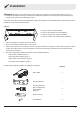
Owner's Manual DSH Series Infrared Heater DSH Series Ceiling Bracket DSH Series Tower Model DSH20W DSHCMB DSHSTAND IMPORTANT SAFETY INFORMATION: Always read this manual first before attempting to install or use this heater. For your safety, always comply with all warnings and safety instructions contained in this manual to prevent personal injury or property damage. To view the full line of Dimplex products, please visit www.dimplex.
Table of Contents Welcome & Congratulations . . . . . . . . . . . . . . . . . . . . . . . . . . . . . . . . . . 3 IMPORTANT INSTRUCTIONS . . . . . . . . . . . . . . . . . . . . . . . . . . . . . . . . 4 Specifications . . . . . . . . . . . . . . . . . . . . . . . . . . . . . . . . . . . . . . . . 5 Site Selection . . . . . . . . . . . . . . . . . . . . . . . . . . . . .
Welcome & Congratulations Thank you and congratulations for choosing to purchase a Dimplex indoor/outdoor infrared heater. Please carefully read and save these instructions. CAUTION: Read all instructions and warnings carefully before starting installation. Failure to follow these instructions may result in a possible electric shock, fire hazard and will void the warranty. Please record your model and serial numbers for future reference.
IMPORTANT INSTRUCTIONS When using electrical appliances, precautions should always be followed to reduce the risk of fire, electric shock, and injury to persons, including the following: ⑬ This equipment shall be installed only by qualified personnel who are familiar with the construction and operation of the apparatus and hazard involved. ② Use this heater only as described in this manual. Any other use not recommended by the manufacturer may cause fire, electric shock, or injury to persons.
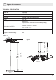
2 Specifications TECHNICAL SPECIFICATION Model No. DSH20W Voltage 240V 60Hz Controller Remote control and optional timer Power 2000 W Installation Wall mount (optional tower or ceiling bracket sold separately) 596 mm x 326 mm x 154 mm Dimensions (LxWxH) 23.5" x 12.8" x 6.1" Insulation Class I Ingress Protection Rating IP65 Figure 1 12.6” 320 mm 355-610 mm 14”-24” 110.2” 2800 mm 103.9” 2640 mm 303 mm 11.9” Figure 2 322mm 12.7” 500 mm 19.
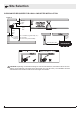
(29.5") Min. (59") Min. 260 mm (10.2") Min. 910 mm (35.4") Min. to surfaces (e.g. table tops, etc.) 2.4 m (94.5") Min. from floor 3 m (118") Max. from floor (recommended) Site Selection 750 mm (29.5") Min. CLEARANCES REQUIRED FOR A WALL-MOUNTED INSTALLATION Figure 3 260 mm (10.2") Min. 1.5 m (59") Min. 95 mm (3.7”) Min. 1 m (39") 2.4 m (94.5") 3 m (118") Min. to surfaces (e.g. table tops, etc.) Min. from floor Max. from floor (recommended) 260 mm (10.2") Min. 750 mm (29.5") Min.
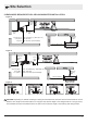
Site Selection CLEARANCES REQUIRED FOR A CEILING-MOUNTED INSTALLATION Figure 4 260 mm (10.2") Min. 750 mm (29.5") Min. 1.5 m (59") Min. 260 mm (10.2") Min. 910 mm (35.4") Min. to surfaces (e.g. table tops, etc.) 2.4 m (94.5") Min. from floor 3 m (118") Max. from floor (recommended) 750 mm (29.5") Min. Figure 5 260 mm (10.2") Min. 4m (157.5") Min. 260 mm (10.2") Min. 1.5 m (59") Min. 1.5 m (59") Min. 95 mm (3.7”) Min. 910 mm (35.4") Min. to surfaces (e.g. table tops, etc.) 2.4 m (96") Min. Min.
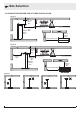
95Min Site Selection CLEARANCES REQUIRED FOR A TOWER INSTALLATION Figure 7 260 mm (10.2") Min. 260 mm (10.2") Min. 1500 mm (59") Min. 1500 mm 2400 mm (59") (94.5") Min. 2400 mm Min. (94.5") Min. 750 mm (29.5") Min. 260 mm (10.2") 260Min. mm (10.2") Min. 750 mm (29.5") Min. Figure 8 4m (157.5") 4m Min. (157.5") Min. 260 mm (10.2") 260 mm Min. (10.2") Min. 1500 mm (59") 1500 mm Min. (59") 2400Min. mm (94.5") 2400 mm Min. (94.5") Min. 750 mm (29.5") Min. 260 mm (10.2") 260Min. mm (10.2") Min.
Installation WARNING: Mounting of the infrared heater and its connection to the electric mains should be carried out only by qualified professionals according to the Electrical Installation Regulations and Power System Safety Standards and comply with all national and local electrical codes. This heater comes with a stainless steel adjustable angle mounting bracket.
Installation WALL-MOUNTED INSTALLATION 1. Install the mounting bracket on the wall using 4 sleeve anchors. Insert them through the holes labeled A in Figure 9. CAUTION: Depending on material and design of ceiling structural elements, the heater must be secured with the correct fasteners. The weight of the DSH heater is 3.75 kg (8.27 lbs) . The installation structure and hardware must be able to hold 5 times the weight of the heater. 2.
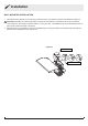
Installation CEILING INSTALLATION Ceiling installation of the DSH heater MUST be performed using the ceiling bracket accessory DSHCMB (sold seperately). This ceiling bracket accessory allow for installation of one or two DSH infrared heaters on the ceiling. This bracket can be installed indoors or outdoors. Cables can be passed within the center of the bracket. The telescopic pole can be adjusted for four different heights, ranging from 35.5 cm (14") to 61 cm (24").
Installation TOWER INSTALLATION DSHSTAND is an optional tower available for the DSH20W infrared heater. This tower can be installed indoors or outdoors. If power cables are accessed from the bottom, they can be passed through the inner diameter of the tower. It is recommended to do this during the second step of installation, when the poles are being assembled. Refer to your local electrical code for information on the appropriate cables for your application.
Installation TOWER ASSEMBLY INSTRUCTIONS FOR A SINGLE HEATER A 1 B 21 C E E D F Attach the pole that has three holes at the bottom to the base. 31 G Remove the rubber ring from the pole. Remove the rubber cap from the top pole. 41 I Secure the bracket using holes labeled "C" in Figure 9. 51 61 71 Secure using hardware suitable for your application. J 3X Re-install the rubber cap on the top of the pole.
Installation TOWER ASSEMBLY INSTRUCTIONS FOR TWO HEATERS 21 A 1 B C E E D F Remove the rubber ring from the pole. Remove the rubber cap from the top pole. Attach the lower pole to the base. 31 H 41 I I Fasten the hardware loosely. Do not tighten at this step. Secure the bracket using holes labeled "B" in Figure 9. 51 71 Re-install rubber stopper and tighten the bracket hardware from the previous step. Secure using hardware suitable for your application.
Wiring Instructions WARNING • This Heater MUST be permanently installed and hard wired by an authorized / licensed electrical professional. • Disconnect electric power supply before working on circuit wiring to prevent electric shock. • When installing outdoors we recommend the heater is positioned where it will be protected from exposure to extreme weather such as snow and ice. • This heater must be grounded. • Electrical connection must have ground fault protection (GFCI or GFI).
Operating Instructions WARNING: The heater must be properly installed before it is used. Slight crackles may be heard during the heating or cooling period. This is a normal part of the operation of the heater. Power Power/On Timer (Hours) Power Timer(Hours) Power Timer Power Timer Low Med High Power 2hr 1hr Timer 4 1hr 2 2hr 1 H 2 4 6 M 1 6 L L M H 1hr 2hr on Standby off 1. S witch on the circuit breaker. The heater will begin in Standby mode.
Maintenance ELECTRIC SHOCK HAZARD • Potentially lethal voltages are present. Be sure to turn off the unit at the circuit breaker before attempting any maintenance. RISK OF INJURY/BURN • Do not attempt to service or clean heater while unit is operating, as there is a hazard from electric shock, and injury potential from hot heating elements. To avoid the risk of burn or injury wait a minimum of 6 hours for the heater to cool before attempting to clean or service.
Troubleshooting Troubleshooting prior to calling a service technician: SYMPTOM RECOMMENDED ACTION Will not heat / No operation indicator LED Check that power is connected and switched on Heater smells when first used This is caused by oil or dust left over from the manufacturing process and will stop after a short time Faint smell for short periods after turning on the heater This is normal and should stop after a short time Heater smells when turned on after periods of non-use This is the result o
Warranty One Year Limited Warranty Products to which this limited warranty applies This limited warranty applies to your newly purchased Dimplex Infrared Indoor/Outdoor Heater. This limited warranty applies only to purchases made in any province of Canada except for Yukon Territory, Nunavut, or Northwest Territories or in any of the 50 States of the USA (and the District of Columbia) except for Hawaii and Alaska.
Technical Support Technical and troubleshooting support, as well as a list of replacement parts can be found on www.dimplex.com/customer_support 1-888-346-7539 | www.dimplex.com In keeping with our policy of continuous product improvement, we reserve the right to make changes without notice.
Manuel d'utilisation Chaufferette infrarouge intérieure / extérieure de la série DSH Support de plafond de la série DSH Tour de la série DSH Modèles DSH20W DSHCMB DSHSTAND CONSIGNES DE SÉCURITÉ IMPORTANTES : Lire le présent manuel avant d’essayer d’installer ou d’utiliser cet appareil. Pour votre sécurité, toujours respecter tous les avertissements et suivre les consignes de sécurité données dans le présent manuel afin de prévenir les blessures ou les dommages matériels.
Table des matières Welcome & Congratulations . . . . . . . . . . . . . . . . . . . . . . . . . . . . . . . . . . 3 INSTRUCTIONS IMPORTANTES . . . . . . . . . . . . . . . . . . . . . . . . . . . . . . 4 Specifications . . . . . . . . . . . . . . . . . . . . . . . . . . . . . . . . . . . . . . . . 5 Choix de l’emplacement . . . . . . . . . . . . . . . . . . . . . . . . . . . .
Bienvenue Merci et félicitations d’avoir acheté un appareil de chauffage infrarouge Dimplex. Lire ces instructions attentivement et les conserver. MISE EN GARDE : Lire attentivement toutes les instructions et tous les avertissements avant de commencer l’installation. Le non-respect de ces instructions pourrait entraîner un risque de décharge électrique ou d’incendie et annuler la garantie. Prendre en note les numéros de modèle et de série de l’appareil à des fins de consultation ultérieure.
INSTRUCTIONS IMPORTANTES Lorsqu’un appareil électrique est utilisé, il est important de toujours prendre des précautions de base pour réduire les risques d’incendie, de décharges électriques et de blessures. Il faut notamment appliquer ce qui suit : ① Lire toutes les instructions avant d’installer ou d’utiliser cet appareil de chauffage. ② Se servir de l’appareil uniquement de la façon décrite dans le présent manuel.
2 Spécifications SPÉCIFICATIONS TECHNIQUES Numéro de modèle DSH20W Tension 240V 60Hz Commandes Télécommande avec fonction de minuterie Puissance 2000 W Installation Murale (Support de fixation au plafond et tour vendus séparément) 596 mm x 326 mm x 154 mm Dimensions (LxlxH) 23.5 po x 12.8 po x 6.1 po Class de protection électrique Classe I Indice de protection IP65 Figure 1 12,6 po 12.6” 320 mm 355-610 mm 14 à 24 po 14”-24” 2800 mm 110,2 110.2”po 103,9 103.
(29.5") Min. (59") Min. 260 mm (10.2") Min. 910 mm (35.4") Min. to surfaces (e.g. table tops, etc.) 2.4 m (94.5") Min. from floor 3 m (118") Max. from floor (recommended) Choix de l’emplacement 750 mm (29.5") Min. DÉGAGEMENTS MINIMAUX POUR INSTALLATION AU MUR Figure 3 260 mm (10,2 po) (10.2") Min. 1,5 1.5 m m (59 po) (59") NE PAS situer les ventilateurs, les lumières et les gicleurs en-dessous du radiateur. Min. 95 mm (3,7 po) (3.7”) Min. surfaces(e.g. (e.g.table tables, etc.)etc.) Min.
Choix de l’emplacement DÉGAGEMENTS MINIMAUX POUR INSTALLATION AU PLAFOND Figure 4 260 mm mm 260 (10,2 po) (10.2") Min. min. NE PAS situer les ventilateurs, les lumières et les gicleurs en-dessous du radiateur. 1,5 m m 1.5 (59 po) (59") min. Min. Plafond aux surfaces (e.g.(e.g. tables, etc.) to surfaces table tops, etc.) 910 (35,4 po) Min. 910mm mm (35.4") au solfrom floor 2,4 m (39 po) Min. 2.4 (94.5") au solfrom (recommandé) 3m (118 po) Max. floor (recommended) 3m (118") 260mm mm 260 (10.
95Min Choix de l’emplacement DÉGAGEMENTS MINIMAUX POUR INSTALLATION AVEC LA TOUR 260 mm (10.2") Min. 260 mm 260 mm (10,2 po) (10.2") min. Min. 1500 mm (59") Min. 1,5 m 1500 mm 2400 mm (59 po) (59") (94.5") min. Min. Min. 2,4 mm m 2400 (94,5 po) (94.5") min. Min. NE PAS situer les ventilateurs, les lumières et les gicleurs en-dessous du radiateur. 260 mm (10.2") 260Min. mm 260 mm (10,2 po) (10.2") min. Min. Plafond Mur Figure 7 750 mm (29.5") Min. 750 mm (29.5") Min.
Installation AVERTISSEMENT : L’installation de l’appareil de chauffage infrarouge et son raccordement au réseau électrique doivent être effectués uniquement par des professionnels qualifiés conformément aux réglementations sur les installations électriques et aux normes de sécurité des systèmes électriques et doivent être conformes à tous les codes électriques nationaux et locaux.
Installation INSTALLATION MURALE 1. Installer le support de fixation au mur en se servant de quincaillerie convenable pour l'application. Les traverser par les trous désignés par la lettre A à la figure 9. VERTISSEMENT : Selon le matériau et la conception des éléments de structure du mur, l’appareil doit être installé A au moyen de matériel de fixation approprié. Le poids de l'appareil DSH est de 3,75 kg (8,27 lb).
Installation INSTALLATION AU PLAFOND Il est obligatoire d'utiliser le support de fixation au plafond DSHCMB (vendu séparément) pour l'installation de l'appareil DSH au plafond. Ce support accessoire permet d'installer un ou deux appareils de chauffage infrarouge au plafond. Ce support peut être installé à l'intérieur ou à l'extérieur. Les câbles électriques peuvent être dissimulés en les passant à l'intérieur du support.
Installation INSTALLATION DE LA TOUR Le DSHSTAND est une tour accessoire qui permet l'installation de un ou deux appareil(s) de chauffage infrarouge DSH20W. Cette tour peut être installée à l'intérieur ou à l'extérieur. Si les câbles électriques sont accédés par le bas, ceux-ci peuvent traverser le diamètre interne de la tour. Il est conseillé que cela se fasse lors de la deuxième étape de l'installation, lorsque les poteaux sont réunis.
Installation INSTALLATION DE LA TOUR AVEC UN APPAREIL DSH A 1 B 21 C E E D F the rubbersupérieur. ring from the pole. Retirer l'embout de caoutchoucRemove du poteau Fixer le poteau inférieur à la base. 31 G 41 I Fixer le support en se servant des trous désignés par la lettre C à la figure 9. 51 61 71 K J 3X Réinstaller l'embout en caoutchouc et serrer la quincallerie du support de l'étape précédente.
Installation INSTALLATION DE LA TOUR AVEC DEUX APPAREILS DSH 21 A 1 B C E E D F Remove the rubber ring from the pole. Retirer l'embout de caoutchouc du poteau supérieur. Fixer le poteau inférieur à la base. 31 H 41 I I Ne pas trop serrer la quincallerie à cette étape. Fixer le support en se servant des trous désignés par la lettre B à la figure 9. 51 71 Réinstaller l'embout en caoutchouc et serrer la quincallerie du support de l'étape précédente.
Instructions de raccordement AVERTISSEMENT • Cet appareil DOIT être installé et directement raccordé au réseau électrique de façon permanente par un professionnel de l’électricité autorisé/agréé. • Couper la source d’alimentation électrique avant de manipuler le câblage du circuit pour prévenir les décharges électriques.
Utilisation AVERTISSEMENT : Cet appareil doit être installé correctement avant son utilisation. De légers craquements peuvent être entendus pendant la période de chauffage ou de refroidissement. Il est normal d’entendre ces craquements pendant le fonctionnement de l’appareil. Power Power/On Timer (Hours) Power Timer(Hours) Power Timer 4 1hr 2 2hr 1 H 2 4 6 M 1 Power 6 L Power L M Timer H 1hr 2hr 1. M ettre le disjoncteur en position de marche; l’appareil se mettra en mode Veille.
Entretien RISQUE DE DÉCHARGES ÉLECTRIQUES • Cet appareil fonctionne à une tension pouvant causer la mort. S’assurer de couper l’alimentation électrique au niveau du disjoncteur avant de tenter de faire un quelconque entretien. RISQUE DE BLESSURE ET DE BRÛLURE • Ne pas tenter de nettoyer ou de réparer le radiateur lorsqu'il est en marche, car cela comporte des risques de décharges électriques et de blessures en raison de l'élément chauffant.
Dépannage Actions de dépannage à effectuer avant d’appeler un technicien en entretien et en réparation : SYMPTÔME ACTION RECOMMANDÉE L’appareil ne chauffe pas. / Il n’y a aucun voyant de fonctionnement DEL S’assurer que l’appareil est bien branché au réseau électrique et qu’il est bien sous tension. L’appareil émet une odeur lors de la première utilisation. Ce phénomène est causé par l’huile ou la poussière laissée pendant le processus de fabrication et s’arrêtera après une courte période.
Garantie Garantie limitée d’un an Produits couverts par la présente garantie limitée La présente garantie limitée couvre votre nouvel appareil de chauffage infrarouge intérieur/extérieur de Dimplex. La présente garantie limitée ne s’applique qu’aux achats effectués dans l’une des provinces du Canada, à l’exception du Yukon, du Nunavut et des Territoires du Nord-Ouest, ou dans l’un des 50 États américains (incluant le district fédéral de Columbia), à l’exception d’Hawaï et de l’Alaska.
Service d'assistance technique Vous trouverez du soutien technique et des instructions de dépannage, ainsi qu'une liste de pièces de rechange à www.dimplex.com/customer_support 1 888 346-7539 | www.dimplex.com Dans le cadre de notre politique d’amélioration continue de nos produits, nous nous réservons le droit de modifier les spécifications sans préavis.