
Owner's Manual

7
FRONT
üüü
(30.0 mm)
1.2 in.
(30.0 mm)
3.5 in.
(90.0 mm)
3.1 in.
(80.0 mm)
4.8 in.
(122.0 mm)
5.4 in.
(137.0 mm)
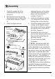
Installation
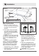
Figure 2
New Construction
1. Mark the desired location on
the oor and store the replace
in a safe, dry and dust free
location.
2. Use studs to frame an enclo-
sure with the following mini-
mum internal/opening dimen-
sions (Figure 2).
!
NOTE: An air inlet is required
for optimum mist production, see
Figure 2 for minimum dimen-
sions.
!
NOTE: For optimal perfor-
mance, the following minimum
clearances between the instal-
lation surface and any surface
above should be maintained:
• Cassette Only: 12 in. (305 mm)
• Cassette with Dimplex heater:
19 in. (483 mm)
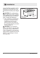
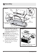
Figure 3
3. Secure unit through the two
holes in the bottom of the unit
into supports to prevent the
unit from hanging from the top
ange, see gure 3 for dimen-
sions.
4. The unit is equipped with a
power supply plug and a fused
receptacle (Figure 4), the plug
should be plugged directly into
a 15 A, 120 V outlet.
CAUTION: During operation
8.5 in.
(216mm)
6.7 in.
(170mm)
Air Inlet
DFI400: 100cm
2
DFI600: 150cm
2
Supports: 0.75 in (19 mm) high
Exit for Cord
DFI400: 15.75 in. (400mm)
DFI600: 22.05 in. (560mm)
Installation
Surface