
Installation Sheet

www.dimplex.com2
3. Remove the desired knockout from the terminal box.
!
NOTE: It is only necessary to remove the knockout(s) that
will feed the power supply wiring, keeping in mind the heater
mounting location and supply wire location.
4. Hang the heater from the hooked edge of the mounting
bracket and proceed to the wiring instructions.
Hanging Mount (Threaded Rod)
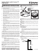
1. Unpack the heater from the carton, remove the two screws
securing the bracket to the unit and remove the screws
securing the terminal box cover. (Figure 1)
CAUTION: Care should be taken when removing the termi-
nal box cover, as the electrical connections are attached to it.
!
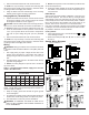
NOTE: See Figure 2 for minimum clearances for the unit.
2. There are four brackets on the top surface of the unit with
1/2 in. (13 mm) holes which can be used to suspend the
unit from an open ceiling using 3/8” (9.5 mm) threaded
rod.
3. Remove the desired knockout from the terminal box.
!
NOTE: It is only necessary to remove the knockout(s) that
will feed the power supply wiring, keeping in mind the heater
mounting location and supply wire location.
Wiring
WARNING: Wiring procedures and connections should be
in accordance with the National Electric Code (NEC) and local
codes.
1. Run supply wiring of proper voltage and wire size to the
location of the terminal box of the heater. (See Table 2)
Supply wiring should be enclosed in 1/2 in. (13 mm) con-
duit.
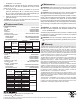
2. Wire all heaters and controls in accordance with the ap-
propriate wiring diagram.
!
NOTE: The wiring diagram for specic unit is located on
top of the heater.
Table 2 - Recommended minimum supply wire sizes are
listed in the table below:
MAXIMUM WATTS PER CIRCUIT USING 75 °C WIRE
(COPPER WIRE)
Rough in
Wire Size
120V 208V 240V 277V 347V 480V 600V
14 1440 2496 2880 3324 4164 5760 7200
12 1920 3328 3840 4432 5552 7680 9600
10 2880 4992 5760 6648 8328 11520 14400
!
NOTE: Supply wire entry is commonly made into one
heater. Though wiring (factory furnished) can be used for con-
nection to adjacent heaters.
3. Wrap the supply ground wire around the green ground
screw and tighten.
4. Do a nal and complete check of all wiring then replace the
terminal box covers being careful not to pinch any wires.
5. The terminal box covers may now be reinstalled.
WARNING: TO PREVENT THE RISK OF FIRE OR IN-
JURY, DO NOT OPERATE THE HEATER UNLESS IT IS
FULLY ASSEMBLED.
!
NOTE: The inspection cover is intended to provide access
for electrical inspections.
6. Swing the heater upwards to secure the opposite side of
the heater to the bracket and secure with previously re-
moved screws.
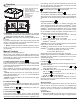
Initial Set Up
After the unit has been installed, calibration of the unit to the
area will be required. This can be done by closing all doors
and windows to the room and turning the unit ON. When the
unit is initially turned on there is a 28 minute period of calibra-
tion of the unit where the software runs at full power for 20
minutes, then runs for 8 minutes to cool the heater down.
If the unit is relocated or the size of the area that it is installed
in changes, it is recommended that the unit be reset to the fac-
tory default to allow the unit to recalibrate.
Factory Default
1. Press and hold the V for 3 seconds. Both the and
icons will begin to ash.
2. Within 5 seconds press ✚, then ✚, then –, then –, then
V, then –.
Sample Wiring Diagrams
240V 347/600V
20A
CONTACTOR
L3
T1
L1
DISPLAY BOARD
10
13
T1
TB3
1
6
TB1
7
600V 3/4/5KW 3PH
TRANSFOMER
FAN
MOTOR
20A
CONTACTOR
11
3
9
T3/FAN HIGH
SENSOR
T2/FAN NEUTRAL
T1/FAN LOW
TB2
G
4
L1
8
L1
14
12
POWER BOARD
5
2
T4/L2
L2
H1
H2 H3
14
13
12
11
10
9
8
7
6
5
2
1
4
3
SENSOR
G
240V 3/4/5KW 3PH
L3
L1
14
13
12
11
10
9
8
7
6
5
2
1
4
3
SENSOR
G
240V 2/3/4/5KW 1PH
L2
L1
FAN
MOTOR
T4/L2
T2/FAN NEUTRAL
T3/FAN HIGH
T1/FAN LOW
TB2
TB3
TB1
POWER BOARD
DISPLAY BOARD
FAN
MOTOR
T4/L2
T2/FAN NEUTRAL
T3/FAN HIGH
T1/FAN LOW
TB2
TB3
TB1
POWER BOARD
DISPLAY BOARD
L2
CUTOUT
CUTOUT
CUTOUT
H3
H2
H1
H3
H2
H1
CUTOUT
DISPLAY BOARD
10
13
TB3
1
6
TB1
7
TRANSFOMER
MOTOR
FAN
11
3
9
T3/FAN HIGH
SENSOR
T2/FAN NEUTRAL
T1/FAN LOW
TB2
G
4
8
L1
14
12
POWER BOARD
5
2
T4/L2
L2
347/600V 3/4/5KW 1PH
H3
H1
L1
T1
H2
L1
T1
CONTACTOR
20A
CONTACTOR
20A
347/600V240V
CUTOUT
480V/600V
240V
CUTOUT
277V/347V/480V/600V
240V
CUTOUT
CUTOUT
4
13
1
H1
L1
14
TB3
7
TRANSFOMER
208V 7.5/10KW 3PH
T1
11
T2/FAN NEUTRAL
7
FAN
MOTOR
POWER BOARD
L3
T3/FAN HIGH
4
5
T4/L2
9
9
SENSOR
11
T2/FAN NEUTRAL
POWER BOARD
H3
T1
T1/FAN LOW
T4/L2
6
TB1
3
12
L2
L1
TRANSFOMER
TB2
G
H3
L1
DISPLAY BOARD
DISPLAY BOARD
1
2
H1
5
12
L1
8
13
T1
6
TB2
G
10
3
T3/FAN HIGH
8
L2
10
TB1
L1
H2
L1
T1
2
TB3
SENSOR
14
H2
208V/240V 7.5/10KW 1PH
T1/FAN LOW
L3
H1
TB3
SENSOR
T1/FAN LOW
TB3
5
3
5
L1
13
DISPLAY BOARD
TB1
TB1
9
10
6
9
T1
10
1
SENSOR
TB2
H1
L1
13
T1
DISPLAY BOARD
6
H2
T3/FAN HIGH
POWER BOARD
T1
T1/FAN LOW
L2
2
11
T3/FAN HIGH
8
H3
L1L1
12
H3
1
12
14
14
T2/FAN NEUTRAL
2
L1
3
TB2
8
G
H2
7
T4/L2
7
T1
4
POWER BOARD
11
L2
G
T2/FAN NEUTRAL
T4/L2
4
L1
277V/347V/480V/600V 7.5/10KW 3PH
480V/600V 7.5/10KW 1PH
30A
CONTACTOR
40A
CONTACTOR
CONTACTOR
40A
CONTACTOR
30A
CONTACTOR
20A
CONTACTOR
30A
20A
CONTACTOR
20A
CONTACTOR
MOTOR
FAN
FAN
MOTOR
MOTOR
FAN