
Owner's Manual
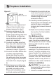
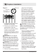
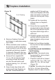
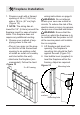
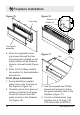
Table Of Contents
15
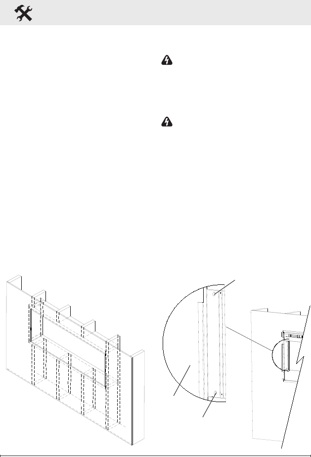
Figure 13
2 x 8 Framing
Fireplace Installation
1. Prepare a wall with a framed
opening of 49 in. (124.5 cm)
wide x 18½ in. (47 cm) high
(Figure 13).
!
NOTE: The sizing has al-
lowed for 1/4” (6.4mm) around the
replace insert for ease of instal-
lation. This replace does not
require any additional venting.
2. Choose your method of sup-
plying power to the unit:
• Plug in (you may run the pow-
er cord out of the framed wall
opening to an existing outlet
or install an outlet on a nearby
wall stud within the wall).
• Hard wire the replace (rec-
ommended). Follow the hard
wiring instructions on page 9.
WARNING: Do not attempt
to wire your own new outlets or
circuits. To reduce the risk of re,
electric shock or injury to persons,
always use a licensed electrician.
WARNING: Ensure that the
circuit on which the replace is to
be installed has the power cut off
at the service panel until installa-
tion is complete.
3. Lift replace and insert into
opening. The replace's
mounting trim should be ush
against the wall (Figure 14).
4. Use bubble level (supplied) to
level the replace within the
framing. Adjust as required.
Figure 14
Mounting hole
Mounting hole
Wall
surface