
Owner's Manual
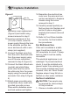
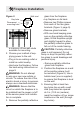
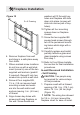
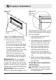
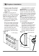
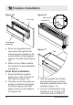
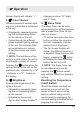
Table Of Contents
11
Figure 8
Hole for
Ground Screw
Fireplace Installation
hard-wire cover replacement
(Figure 8) and install using
screws removed in step 2.
10. Leaving a minimum of 3 in.
(7.6 cm) of slack, route the
power supply through the hole
in the alternate junction box
cover and secure with a wire
clamp (not supplied).
11. Connect the black wire (live)
from the unit to the black wire
from the power supply using
one of the wire connectors
removed in step 5 (Figure 6).
12. Connect the black ribbed wire
(neutral) and white icker
motor wire from the unit to
the white wire from the power
supply using the second wire
connector from step 5 (Figure
6).
13. Attach green grounding wire
to hard wire cover cover with
provided grounding screw.
Place wire in-between screw
and lock washer and tighten.
14. Reposition the electrical box
cover over the wires and con-
nectors and attach to replace
chassis using the screw
removed in step 3.
15. Carefully reinsert partially re-
ective glass into replace and
anchor in place using glass
brackets and screws removed
in step 1.
16. Refer to Front Glass Installa-
tion section, for nal installa-
tion procedures.
For Bathroom Use
If this unit is installed in a bath-
room it must be protected by a
GFI receptacle or circuit. If recep-
tacle is used it must be readily
accessible.
This electrical applicance is not
watertight. To prevent electrical
shock, it must be installed as to
prevent water from entering unit.
This must be installed away from
showers, tubs, etc. Never locate
replace where it may fall into a
bathtub or other water container.
Surface Installation
CAUTION: Two people may
be required for various steps
of this procedure.
1. Choose a location which has