
Service Manual
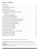
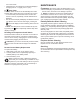
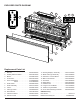
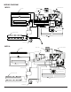
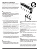
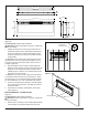
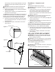
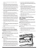
Table Of Contents
- Operation
- Maintenance
- Exploded Parts Diagram
- Wiring Diagram
- Preparation for Service
- Instructions for Removing from Wall
- LED light Strips Replacement
- LED Media Strips Replacement
- Electronics Junction Board Replacement
- Floating Display Assembly Replacement
- LED Driver Board Replacement
- Main Control Board Replacement
- Relay Board Replacement
- Thermistor Replacement
- Switchboard Replacement
- Element Replacement
- High Temperature Cutout Replacement
- Blower/Fan Replacement
- Power Cord Replacement
- Troubleshooting Guide

9
inner casing on the left and right hand side. There are
2 screws per side, upper and lower going into a stud.
(Figure 8)
CAUTION: The replace should be supported while
removing the screws to prevent the unit from falling.
2. Remove the replace out of the opening by slightly lift-
ing and pulling forward.
3. Carefully lay the unit down on a solid at surface with
the front of the unit facing up.
!
NOTE: If the surface you are using as a work area is a
nished surface that is prone to scratches (i.e. hardwood
ooring), it is recommended that a protective barrier be
used underneath, (i.e. cloth, cardboard, thick plastic).
4. Proceed to the instructions within this manual relating
to the repair being performed - see Table of Contents
for page number.
5. Once repair is complete, reassemble in the reverse
order as above.
Flush Mount – Complete In-wall
(Figure 9)
Tools Required: Philips head screwdriver
CAUTION: Follow “Preparation for Service” instructions
before proceeding.
1. Locate and remove the 4 mounting screws inside the
unit located on left and right side towards the front.
There are 2 screws per side, going from the side
panels out into the side of the wall stud that frames the
replace. (Figure 9)
CAUTION: The unit should be supported while remov-
ing the screws to prevent the unit from falling.
2. Remove the replace out of the opening by slightly lift-
ing and pulling forward.
3. Carefully lay the unit down on a solid at surface with
the front of the unit facing up.
!
NOTE: If the surface you are using as a work area is a
nished surface that is prone to scratches (i.e. hardwood
ooring), it is recommended that a protective barrier be
used underneath, (i.e. cloth, cardboard, thick plastic).
4. Proceed to the instructions within this manual relating
to the repair being performed - see Table of Contents
for page number.
5. Once repair is complete, reassemble in the reverse
order as above.
LED LIGHT STRIPS REPLACEMENT
WARNING: Disconnect power before attempting any
maintenance or cleaning to reduce the risk of electric
shock or damage to persons.
CAUTION: If unit was operating prior to servicing allow
at least 10 minutes for lights and heating elements to cool
off to avoid accidental burning of skin.
Tools required: Phillips head screwdriver
Wire snips
CAUTION: Follow “Preparation for Service” instructions
before proceeding.
1. Remove the plastic media tray by removing the 6
Mounting Holes
Figure 8
Wall Surface
Mounting Hole
Figure 9
Figure 10
Front Panel
Front Panel tabs (2)
Media Tray screws (6)