
Service Manual
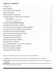
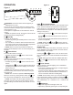
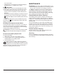
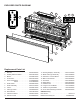
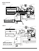
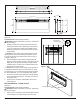
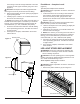
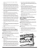
Table Of Contents
- Operation
- Maintenance
- Exploded Parts Diagram
- Wiring Diagram
- Preparation for Service
- Instructions for Removing from Wall
- LED light Strips Replacement
- LED Media Strips Replacement
- Electronics Junction Board Replacement
- Floating Display Assembly Replacement
- LED Driver Board Replacement
- Main Control Board Replacement
- Relay Board Replacement
- Thermistor Replacement
- Switchboard Replacement
- Element Replacement
- High Temperature Cutout Replacement
- Blower/Fan Replacement
- Power Cord Replacement
- Troubleshooting Guide

8 www.dimplex.com
Surface Mount
(Figure 6)
Tools Required: Philips head screwdriver
CAUTION: Follow “Preparation for Service” instructions
before proceeding.
1. Partially unscrew the rear mounting screws that are
holding the replace to the wall along the back panel
of the unit. Support the weight of the replace when
loosening the screws so unit does not fall off the wall
unexpectedly.
!
NOTE: Be sure to take note of which keyhole mount
openings were used for positioning the replace so that
it can be re-placed in the same location when service is
complete. (Figure 6)
2. Take the replace off the wall by carefully lifting the
replace off the mounting screws so they line up to the
larger part of the keyhole openings and pull forward.
Carefully lay the unit down on a solid at surface with
the front of the unit facing up.
!
NOTE: If the surface you are using as a work area on
is a nished surface that is prone to scratches (i.e. hard-
wood ooring), it is recommended that a protective barrier
be used underneath, (i.e. cloth, cardboard, thick plastic).
3. Proceed to the instructions within this manual relating
to the repair being performed - see Table of Contents
for page number.
4. Once repair is complete, reassemble in the reverse
order as above.
Recessed Mount - Partial In-wall
(Figure 7)
Tools Required: Philips head screwdriver
CAUTION: Follow “Preparation for Service” instructions
before proceeding.
1. Remove the 4 mounting screws located approximately
3 inches deep in the space between the outer and
50
5
16
" (128 cm)
19
1
2
(49.5 cm)
46" (116 cm)
48
1
2
" (123 cm)
3" (7.6 cm)
7"
(17.8 cm)
3
13
16
"
(9.7 cm)
18"
(45.7 cm)
16"
(40.6 cm)
Figure 5
Figure 6
Key-hole
Wall stud
Permanent
mounting hole
Mounting Holes
Figure 7