
Service Manual
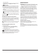
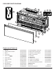
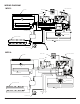
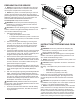
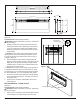
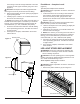
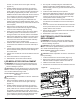
Table Of Contents
- Operation
- Maintenance
- Exploded Parts Diagram
- Wiring Diagram
- Preparation for Service
- Instructions for Removing from Wall
- LED light Strips Replacement
- LED Media Strips Replacement
- Electronics Junction Board Replacement
- Floating Display Assembly Replacement
- LED Driver Board Replacement
- Main Control Board Replacement
- Relay Board Replacement
- Thermistor Replacement
- Switchboard Replacement
- Element Replacement
- High Temperature Cutout Replacement
- Blower/Fan Replacement
- Power Cord Replacement
- Troubleshooting Guide

7
PREPARATION FOR SERVICE
!
NOTE: All components are replaceable from the front
of the replace while the unit is mounted on the wall, with
the exception of replacement of the power cord.
!
NOTE: If the power cord needs replacing or if the unit
needs to be removed from the wall for any other reason
please begin service by following the “PREPARATION FOR
SERVICE” instructions, then move on to the section “IN-
STRUCTIONS FOR REMOVING FROM WALL”.
Tools Required: Philips head screwdriver
WARNING: Disconnect power before attempting any
maintenance or cleaning to reduce the risk of electric
shock or damage to persons.
CAUTION: If unit was operating prior to servicing allow
at least 10 minutes for lights and heating elements to cool
off to avoid accidental burning of skin.
1. Disconnect power source.
• Unplug the replace from the outlet.
• If unit has been hardwired for power or outlet is not
accessible from the front, turn the breaker off at the
electrical panel.
2. Remove the front glass assembly by removing the 2
screws (1 on the left and 1 on the right side, located
just inside the top front vent opening). These screws
secure the front glass panel to the inside of the re-
place. (Figure 4)
3. Lift the front glass assembly off of the 4 mounts located
between the outer and inner casing of the replace: 2
on the left and 2 on the right. (Figure 3) Carefully place
the glass assembly aside in a safe location.
4. Remove the decorative glass ember-bed pieces from
the media tray, which lies along the bottom of the inter-
ior Partially Reective Glass. A medium sized container
such as a bucket or a box will be needed to keep the
glass ember-bed pieces together.
5. Remove the Partially Reective Glass by removing the
2 screws on each bracket; (2-brackets in total), located
on the left and right side of the Partially Reective
Glass.
6. With one hand gently supporting the Partially Reective
Glass, carefully pry the Partially Reective Glass for-
ward from the upper half so that it begins to tilt forward
from the top. Grasp the Partially Reective Glass from
the sides and carefully lift it up and out from the front of
the replace. Set it aside in a safe place.
CAUTION: Partially Reective Glass is not tempered.
Do not bump or drop the Partially Reective Glass to avoid
breakage and personal injury.
7. Proceed to the instructions within this manual relating
to the repair being performed - see Table of Contents
for page number.
INSTRUCTIONS FOR REMOVING FROM
WALL
WARNING: Disconnect power before attempting any
maintenance or cleaning to reduce the risk of electric
shock or damage to persons.
CAUTION: If unit was operating prior to servicing allow
at least 10 minutes for lights and heating elements to cool
off to avoid accidental burning of skin.
!
NOTE: Only required for replacement of the power cord
or removal from service.
CAUTION: Follow “Preparation for Service” instructions
before proceeding.
Mounting - The replace may be mounted in one of 3 meth-
ods:
• Surface Mount
• Recess Mount (partially in the wall)
• Flush Mount (completely in the wall)
Identify the type of mounting and follow the appropriate
instructions in the following pages. (See Figure 5 for the
top and side prole view with measurements of the back
panel).
CAUTION: Two people will be required for removal and
re-installation of the replace. The unit is approx. 50 5/16”w
x 19 1/2”h x 7”d. Weight is approximately 75lbs.
!
NOTE: If replace is hard wired directly to the electrical
panel, and there is not enough slack in the wires within the
wall to reach your work area, remove the electrical junc-
tion box cover located on the bottom right by removing the
1 screw on the front of the cover. Lift the cover off and set
aside. Disconnect the 3 wire connectors connected to the
power source, taking note of their original conguration.
Figure 4
Tab
Figure 3
Hooks (4)
Mounts (4)