
Service Manual
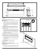
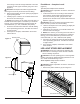
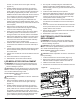
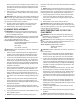
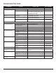
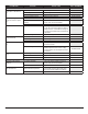
Table Of Contents
- Operation
- Maintenance
- Exploded Parts Diagram
- Wiring Diagram
- Preparation for Service
- Instructions for Removing from Wall
- LED light Strips Replacement
- LED Media Strips Replacement
- Electronics Junction Board Replacement
- Floating Display Assembly Replacement
- LED Driver Board Replacement
- Main Control Board Replacement
- Relay Board Replacement
- Thermistor Replacement
- Switchboard Replacement
- Element Replacement
- High Temperature Cutout Replacement
- Blower/Fan Replacement
- Power Cord Replacement
- Troubleshooting Guide

11
board.
5. Ensure that all cords are replaced in the same manner
as prior to the service.
6. Reassemble in the reverse order as above.
FLOATING DISPLAY ASSEMBLY
REPLACEMENT
WARNING: Disconnect power before attempting any
maintenance or cleaning to reduce the risk of electric
shock or damage to persons.
CAUTION: If unit was operating prior to servicing allow
at least 10 minutes for lights and heating elements to cool
off to avoid accidental burning of skin.
Tools required: Phillips head screwdriver
CAUTION: Follow “Preparation for Service” instructions
before proceeding.
1. Locate the oating display assembly. (Figure 12)
2. Remove the 2 screws securing the board to the mount-
ing bracket.
3. Install the new board onto the unit.
4. Trace the connector from the assembly location to the
electronics junction board, remove the old connection
and replace with the new connector.
5. Ensure that all cords are replaced in the same manner
as prior to the service.
6. Reassemble in the reverse order as above.
LED DRIVER BOARD REPLACEMENT
WARNING: Disconnect power before attempting any
maintenance or cleaning to reduce the risk of electric
shock or damage to persons.
CAUTION: If unit was operating prior to servicing allow
at least 10 minutes for lights and heating elements to cool
off to avoid accidental burning of skin.
Tools required: Phillips head screwdriver
CAUTION: Follow “Preparation for Service” instructions
before proceeding.
1. In the upper right hand corner of the unit, above the
oating display board, locate the control board cover
panel and remove the 2 securing screws. (Figure 11)
1. Locate the LED driver board. (Figure 12)
2. Remove the board by pinching the plastic mounting
tabs with needle nose pliers. Pull the old board off.
3. Install the new board onto the unit.
4. Transfer the connections from the old board to the new
board.
5. Ensure that all cords are replaced in the same manner
as prior to the service.
6. Reassemble in the reverse order as above.
MAIN CONTROL BOARD
REPLACEMENT
WARNING: Disconnect power before attempting any
maintenance or cleaning to reduce the risk of electric
shock or damage to persons.
CAUTION: If unit was operating prior to servicing allow
at least 10 minutes for lights and heating elements to cool
off to avoid accidental burning of skin.
Tools required: Phillips head screwdriver
CAUTION: Follow “Preparation for Service” instructions
before proceeding.
1. In the upper right hand corner of the unit, above the
oating display board, locate the control board cover
panel and remove the 2 securing screws. (Figure 11)
1. Locate the main control board. (Figure 12)
2. Remove the board by pinching the plastic mounting
tabs with needle nose pliers. Pull the old board off.
3. Install the new board onto the unit.
4. Transfer the connections from the old board to the new
board.
5. Ensure that all cords are replaced in the same manner
as prior to the service.
6. Reassemble in the reverse order as above.
RELAY BOARD REPLACEMENT
WARNING: Disconnect power before attempting any
maintenance or cleaning to reduce the risk of electric
shock or damage to persons.
CAUTION: If unit was operating prior to servicing allow
at least 10 minutes for lights and heating elements to cool
off to avoid accidental burning of skin.
Tools required: Phillips head screwdriver
CAUTION: Follow “Preparation for Service” instructions
before proceeding.
1. In the upper right hand corner of the unit, above the
oating display board, locate the control board cover
panel and remove the 2 securing screws. (Figure 11)
1. Locate the relay board. (Figure 12)
Figure 12
LED Driver Board
Electronics Junction
Board
Relay Board
Main Control Board
Floating Display Assembly
Thermistor