
Owner's Manual
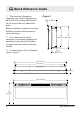
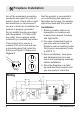
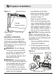
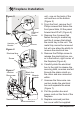
Table Of Contents

10 www.dimplex.com
Black live
wires
Fireplace Installation
unit - one on the back of the
unit and two on the bottom.
(Figure 5)
3. From the front, remove the 2
Philips screws that fasten the
front panel tabs, tilt the panel
forward and lift off. (Figure 4)
4. Remove the 4 screws that
fasten the acrylic media tray
and the 2 screws that attach
the metal tray to the unit. The
metal tray cannot be removed
but will now allow the ability to
remove the electrical box.
5. Remove the Phillips screw to
release the electrical box cov-
er in the bottom, right corner of
the replace (Figure 6).
6. Carefully slide the electrical
box to the right to release the
securing tabs, as wires are fed
through the strain reliefs on
the cover and are connected
within.
7. Unscrew the three wire con-
nectors inside the electrical
box and separate the wires
(Figure 7).
8. Pull the junction box and
power cord out the front of the
replace.
9. Replace removed junction
box cover with the supplied
Figure 7
Wires to
controls
Wire connectors
Junction
Box screw
Neutral wires
Figure 6
Electrical box
Screw
Figure 5
Screws
Hardwire
Bracket
Electrical
Cord
Bracket