
Prism Series Service Manual
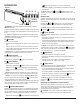
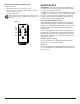
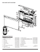
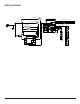
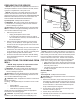
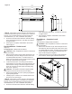
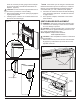
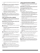
Table Of Contents
- Operation
- Maintenance
- Exploded Parts Diagram
- Wiring Diagram
- Preparation for service
- Instructions for removing from wall
- Switchboard Replacement
- Relay Board Replacement
- AD/DC Adapter Replacement
- Display / Control Board Replacement
- Flicker Motor Replacement
- Flicker Motor/ Flicker Rod Replacement
- LED Light Strips Replacement
- High Temperature Cutout Replacement
- Element Replacement
- Blower/fan Replacement
- Thermistor Replacement
- Troubleshooting Guide

9
There are 2 screws per side, going from the side pan-
els out into the side of the wall stud that frames the
replace. (Figure 8)
CAUTION: The unit should be supported while remov-
ing the screws to prevent the unit from falling.
3. Remove the replace out of the opening by slightly lift-
ing and pulling forward.
4. Carefully lay the unit down on a solid at surface with
the front of the unit facing up.
!
NOTE: If the surface you are using as a work area is a
nished surface that is prone to scratches (i.e. hardwood
ooring), it is recommended that a protective barrier be
used underneath, (i.e. cloth, cardboard, thick plastic).
5. Proceed to the instructions within this manual relating
to the repair being performed - see Table of Contents
for page number.
6. Once repair is complete, reassemble in the reverse
order as above.
SWITCHBOARD REPLACEMENT
WARNING: Disconnect power before attempting any
maintenance or cleaning to reduce the risk of electric
shock or damage to persons.
CAUTION: If unit was operating prior to servicing allow
at least 10 minutes for lights and heating elements to cool
off to avoid accidental burning of skin.
Tools required: Phillips head screwdriver.
Small adjustable wrench
CAUTION: Follow “Preparation for Service” instructions
before proceeding.
1. Remove the 2 screws, that secure the controls assem-
bly (Figure 9), located at the top of the mirror on the
right side of the unit.
Wall Surface
Mounting Hole
Figure 8
Mounting hole
Mounting
holes
Figure 7
Figure 10
Relay Board
Switch
Board
AC/DC
Adapter
Figure 9
Retaining Screws
Controls Assembly