
Service Manual
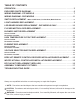
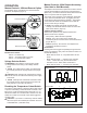
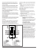
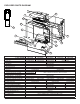
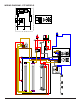
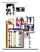
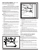
Table Of Contents
- Operation
- Exploded Parts Diagram
- Wiring Diagram - STP Models
- Wiring Diagram - DXP Models
- Switch Replacement - Main On/Off Power; Purifier/Heat; Mode Selector
- Light Harness Replacement
- LED Driver Board Replacement - DXP Models Only
- Flicker Motor & Rod Replacement
- Blower / Motor Replacement
- High Temperature Cutout Replacement
- Element Replacement
- Voltage Selector Switch Replacement
- BFRC-KIT Remote Control Receiver Installation/Replacement
- WRCPF-KIT Wall Controller Installation/Replacement
- BF Plug Kit Replacement (BFPLUGE)
- ASSEMBLY COMPONENT PICTURES
- Troubleshooting Guide

2 www.dimplex.com
Always use a qualied technician or service agency to repair this replace.
!
NOTE: Procedures and techniques that are considered important enough to emphasize.
CAUTION: Procedures and techniques which, if not carefully followed, will result in damage to the
equipment.
WARNING: Procedures and techniques which, if not carefully followed, will expose the user to the
risk of re, serious injury, or death.
OPERATION .........................................................3
EXPLODED PARTS DIAGRAM . . . . . . . . . . . . . . . . . . . . . . . . . . . . . . . . . . . . . . . . . . 6
WIRING DIAGRAM - STP MODELS . . . . . . . . . . . . . . . . . . . . . . . . . . . . . . . . . . . . . . 7
WIRING DIAGRAM - DXP MODELS . . . . . . . . . . . . . . . . . . . . . . . . . . . . . . . . . . . . . . 8
SWITCH REPLACEMENT -
Main On/Off Power; Purier/Heat; Mode Selector . . . . . . . . . . . . . . . .9
LIGHT HARNESS REPLACEMENT .......................................9
LED DRIVER BOARD REPLACEMENT - DXP MODELS ONLY ................10
FLICKER MOTOR & ROD REPLACEMENT . . . . . . . . . . . . . . . . . . . . . . . . . . . . . . . 10
BLOWER / MOTOR REPLACEMENT ....................................11
Secured in Wall . . . . . . . . . . . . . . . . . . . . . . . . . . . . . . . . . . . . . . . . . . . . . . . . . . . . . . . . . . . . . . . . . . . . . . . . 11
Removable from Wall . . . . . . . . . . . . . . . . . . . . . . . . . . . . . . . . . . . . . . . . . . . . . . . . . . . . . . . . . . . . . . . . . . .12
HIGH TEMPERATURE CUTOUT REPLACEMENT ..........................12
Secured in Wall . . . . . . . . . . . . . . . . . . . . . . . . . . . . . . . . . . . . . . . . . . . . . . . . . . . . . . . . . . . . . . . . . . . . . . . .12
Removable from Wall . . . . . . . . . . . . . . . . . . . . . . . . . . . . . . . . . . . . . . . . . . . . . . . . . . . . . . . . . . . . . . . . . . .12
ELEMENT REPLACEMENT ............................................13
Secured in Wall . . . . . . . . . . . . . . . . . . . . . . . . . . . . . . . . . . . . . . . . . . . . . . . . . . . . . . . . . . . . . . . . . . . . . . . .13
Removable from Wall . . . . . . . . . . . . . . . . . . . . . . . . . . . . . . . . . . . . . . . . . . . . . . . . . . . . . . . . . . . . . . . . . . .13
VOLTAGE SELECTOR SWITCH REPLACEMENT . . . . . . . . . . . . . . . . . . . . . . . . . . 14
Secured in Wall . . . . . . . . . . . . . . . . . . . . . . . . . . . . . . . . . . . . . . . . . . . . . . . . . . . . . . . . . . . . . . . . . . . . . . . .14
Removable from Wall . . . . . . . . . . . . . . . . . . . . . . . . . . . . . . . . . . . . . . . . . . . . . . . . . . . . . . . . . . . . . . . . . . .14
BFRC-KIT REMOTE CONTROL RECEIVER INSTALLATION/REPLACEMENT . . . 15
WRCPF-KIT WALL CONTROLLER INSTALLATION/REPLACEMENT . . . . . . . . . . 15
BF PLUG KIT REPLACEMENT (BFPLUGE) ...............................16
ASSEMBLY COMPONENT PICTURES ...................................17
TROUBLESHOOTING GUIDE . . . . . . . . . . . . . . . . . . . . . . . . . . . . . . . . . . . . . . . . . . 19
TABLE OF CONTENTS