
Operation Manual


28 Setup
Dimension BST 768 / SST 768 User Guide
vi. After allowing your PC a minute or so to adjust to the
new setting, your PC should connect to your printer.
vii. If you are still unable to connect to your printer,
recheck your connections and settings. Contact your
local reseller for additional customer service.
Verifying Tip Depth
The system’s tip depth has been set at the factory and normally
does not need adjustment. During shipment, however, tip depth
may shift. Customers that setup and install their own systems need
to verify the tip depth setting prior to building. Building with the
wrong tip depth can result in models not adhering to the modeling
base or a loss of extrusion.
To verify tip depth:
1. Install an unused modeling base.
2. Load Model and Support material (see “Loading Material” on
page 34.
3. Press Maintenance.
4. Press Test Parts, and select test_tipdep_plstc.cmb.
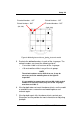
The printer will create six groups of numbers on the modeling
platform. Each individual group will consist of four number
pairs. Each number pair will have an extruded number and an
etched number. Each number pair is created at one of four Z-
heights: -5, 0, +5, and +10 (in .001 inches from ‘home’ level).
See Figure 8 on page 29.
NOTE
The etched number is created by the idle tip. It is normal for only
some of these numbers to be visible.
The extruded number is created at a very low flow rate and may
not show up clearly.