BST 768 / SST 768 User Guide
Notice The information in this document is subject to change without notice. STRATASYS, INC. MAKES NO WARRANTY OF ANY KIND WITH REGARD TO THIS MATERIAL, INCLUDING, BUT NOT LIMITED TO, THE IMPLIED WARRANTIES OF MERCHANTABILITY AND FITNESS FOR A PARTICULAR PURPOSE. Stratasys, Inc. shall not be liable for errors contained herein or for incidental or consequential damages in connection with the furnishing, performance, or use of this material.
Introduction Dimension is designed with ultimate simplicity in mind. The system enables you to build parts quickly, even if you’ve never used a 3D printer before. Its display panel prompts you to press a few keys to get you modeling quickly. The system models with ABS plastic, so modeled parts are strong and durable. ABS also ensures you’ll be able to drill, tap, sand, and paint your creations.
How To Use This Manual This User’s Guide is laid out in easy to follow sections which cover Set-up, Operation, Maintenance, and Troubleshooting of your Dimension printer. Be sure to read each section carefully so that you will get the best performance from your system. Highlighted Information The manual is written in a step-by-step format so as to guide you through a variety of operational tasks.
Sections Of The Manual Overview... Provides a quick reference for the layout of the printer and its operating components. Overview also provides a quick reference for sources of additional information and printer supplies. Setup... Guides you through the initial printer installation and setup. Topics include unpacking, connecting power, installing software, and connecting to a computer network. Generally, topics in setup are only accomplished during installation or relocation of the printer. Operation...
Dimension BST 768 / SST 768 User Guide
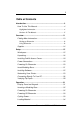
Table of Contents Introduction................................................................................ 3 How To Use This Manual......................................................... 4 Highlighted Information .................................................................. 4 Sections Of The Manual................................................................. 5 Overview................................................................................... 11 Finding More Information ..........
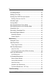
Unloading Material .................................................................37 Building a Test Part ................................................................39 Sending Your CAD File to the System ...................................39 Building a Part from Your File ...................................................... 41 Chamber Lights ......................................................................41 Pausing Build ....................................................................
Troubleshooting Checklist...................................................... 57 Fault Determination Codes .................................................... 59 Loss of Extrusion.................................................................... 59 Diagnosing Loss of Extrusion....................................................... 59 Recovering From Loss of Extrusion .............................................
Dimension BST 768 / SST 768 User Guide
Overview Dimension builds models, including internal features, directly from CAD STL files. The system builds three-dimensional parts by extruding a bead of ABS plastic through a computer-controlled extrusion head, producing high quality parts that are ready to use immediately after completion. With two layer resolution settings, you can choose to build a part quickly for design verification, or you can choose a finer setting for higher quality surface detail.
Overview 3 2 4 1 5 6 Figure 2: Dimension Rear View Item Nomenclature 1 2 3 Fan Cover Main Circuit Breaker Power Cord Adapter Item Nomenclature 4 5 6 Dimension BST 768 / SST 768 User Guide UPS Connection Diagnostic Hookup Network Cable Connection
Overview 13 The Dimension system consists of two primary components — the Dimension 3D printer and CatalystEX. CatalystEX is the preprocessing software that runs on a Windows 2000 or Windows XP Pro platform. Dimension’s build envelope measures 203 x 203 x 305 mm (8 x 8 x 12 in). Each material cartridge contains 922 cc (56.3 cu. in.) of usable material — enough to build continuously for about four days without reloading. Finding More Information Several references are available for use with Dimension.
Overview Supplies This section lists all replaceable supplies used by the Dimension modeling system. The parts mentioned in this list can be obtained by contacting the sales representative through whom you purchased your system.
Setup Workspace Observe the following when placing Dimension in its operating location: • Dimension has an approximate weight of 128 kg (282 lbs.) and requires a table capable of safely supporting 136 kg (300 lbs). • System Dimensions: 914 x 686 x 1041 mm (36 x 27 x 41 in) Four-inch minimum space behind unit for air circulation • Dedicated outlet requirements: 110-120 VAC, 60 Hz, 15 A min. (20 amp recommended) –or– 220-240 VAC, 50/60 Hz, 7 A min.
Setup Unpacking This section describes the recommended procedures for unpacking and preparing Dimension for its first use. Unpack the printer: WARNING The Dimension printer weighs approximately 128 kg (282 lbs). Use proper moving and lifting techniques when positioning the unit. For your convenience, there are forklift pads built into the bottom of the unit. They are accessible from the side of the unit. 1. Before unpacking the printer, move it near to its operating location. 2.
Setup 17 CAUTION Remove the foam tubes that isolate the extrusion head from the frame (see Figure 3). The printer will be damaged if powered on with the foam tubes in place. CAUTION Be careful not to damage the rod sensors when removing the foam tubes (see Figure 3). 8. Remove the foam tubes that isolate the extrusion head from the frame (see Figure 3). Circles indicate Rod Sensor locations. There are also two sensors on the back side of the Extrusion Head.
Setup Installing Forklift Access Covers The forklift access covers can be placed over the forklift channels after the printer is placed in its final location (see Figure 4). The covers are press-fit in the front and held in place with one screw in the rear. Insert Tab in Slot Push Cover Toward Front of Printer Attachment Screw on Back of Printer Figure 4: Installing the forklift access covers Power Connections This section discusses the procedure for preparing all power connections for the printer.
Setup 19 Figure 5: Connecting to a grounded electrical outlet CAUTION Do not use an extension cord or power strip with the Dimension system. Connect the cord directly into the receptacle or UPS. 2. Connect the female end of the power cord directly into the rear of the cabinet. 3. Switch the Dimension circuit breaker to the on (up) position. The Dimension system is now ready to have power applied.
Setup Powering On Dimension WARNING Dimension’s build chamber and extrusion-head tip get very hot! The chamber and head tip reach temperatures of approximately 75° C (167° F) and 280° C (536° F) respectively. Personal injury can occur if proper techniques and safety materials are not used. Use the leather safety gloves provided in the Startup Kit when working inside the printer. CAUTION Remove the foam tubes that isolate the extrusion head from the frame (see Figure 3 on page 17).
Setup 21 NOTE If the printer was off and is at room temperature, it requires approximately 40 minutes to warm up before you can perform any functions. Temperatures are factory-preset and not adjustable. The panel displays the head and envelope temperatures while Dimension is warming up and cooling down. NOTE For safety, the head and Z Platform do not move while the chamber door is open. During warm-up and operation the door is locked.
Setup Installing Software There are two software programs that work with Dimension. • CatalystEX is the preprocessing software that controls Dimension. If you have not already done so, you will need to install the CatalystEX software on your PC. You will find the CatalystEX software on the CD-ROM included in your Startup Kit (See “Install CatalystEX:” on page 22.). • There is also ‘controller’ software loaded directly onto your Dimension system from the factory.
Setup 23 6. Compare the version number to the controller software CD provided in the Startup Kit. 7. If the version on the controller software CD is newer than the system version, follow the Controller Software Upgrade Notice instructions provided in the Startup Kit. Networking Your Printer You will need to establish communication between your PC and printer before you can send files to print. How you establish this communication is dependent upon how your computer network is configured.
Setup B. Click the ‘Add from Network...’ button in the lower right corner of the pop-up. C. A new pop-up, ‘Add 3D Printer’, should list your printer in the main window (identified by its UDN). Click on the printer in this window and enter a Name and Location (your choice) in the lower portion of the pop-up. D. Click ‘Add Printer’ - and you are ready to go. Close the 3D Printer pop-up. NOTE If your printer is not displayed in the ‘Add 3D Printer’ pop-up, you are not using a Dynamic network.
Setup 25 6. Use the three functions above to set your IP address. 7. After setting the final digit of the IP address, move the cursor one more place to the right. The cursor moves to the NM (or Netmask) address. Follow the same steps for setting the NM and GW addresses. 8. When you have finished setting the addresses, press Done. The panel displays Change IP, Netmask, Gateway? 9. Press Yes. The panel then displays Resetting Network and after a moment returns to Idle or starts warming up. 10.
Setup D. Enter the IP Address for your printer in the appropriate field. It will be the same address as the one entered in Step 4. E. Select the appropriate printer type from the drop down list. F. Click ‘Add Printer’ and close the 3D Printer pop-up. 13. If you are unable to connect the printer to your PC, contact your Network Administrator. Connecting Directly To Your PC You can connect the Dimension printer directly to your PC without the use of a network.
Setup 27 C. A new pop-up, ‘Add 3D Printer’, should list your printer in the main window (identified by its UDN). Click on the printer in this window and enter a Name and Location (your choice) in the lower portion of the pop-up. NOTE It may take up to 1 minute for your printer to appear in the pop-up window. D. Click ‘Add Printer’ - and you are ready to go. Close the 3D Printer pop-up. 4. If your printer does not appear in the pop-up window: A.
Setup vi. After allowing your PC a minute or so to adjust to the new setting, your PC should connect to your printer. vii. If you are still unable to connect to your printer, recheck your connections and settings. Contact your local reseller for additional customer service. Verifying Tip Depth The system’s tip depth has been set at the factory and normally does not need adjustment. During shipment, however, tip depth may shift.
Setup 29 Extruded Numbers - SST Etched Numbers - SST Etched Numbers - BST Extruded Numbers - BST (left side) (right side) -5 -5 0 0 +5+5 +10 +10 -5 -5 0 0 +5+5 +10 +10 -5 -5 0 0 +5+5 +10 +10 -5 -5 0 0 +5+5 +10 +10 -5 -5 0 0 +5+5 +10 +10 -5 -5 0 0 +5+5 +10 +10 Figure 8: Modeling base with test_tipdep_plstc.cmb model 5. Evaluate the etched numbers in each of the six groups. The etched numbers must meet the following criteria: • -5 must be visible in at least one of the six groups.
Setup Dimension BST 768 / SST 768 User Guide
Operation Display Panel and Keypad The main User Interface to Dimension is the Display Panel and Keypad (see Figure 9). Display Panel Keypad buttons Contextsensitive displays Figure 9: Dimension display panel and keypad The Dimension display panel and keypad are very easy to use, consisting of a larger multiple-line LCD display on top, and four single-line context-sensitive displays, each with one button (or key). The top line in the large display always reveals the printer status.
Operation Inserting a Modeling Base Prior to inserting a modeling base into the tray, remove any material buildup on and behind the Z Platform and around the lead screw. Failure to do so could cause the modeling base to be unlevel or, if the amount of buildup is large enough, the Z Platform could jam at its upper limit. Install the modeling base (See “Insert Modeling Base” on page 21. - "Setup"). Reusing a modeling base: The square outlines on the modeling base represent modeling areas.
Operation 33 Powering Off Dimension To power-off Dimension, move the power switch to the OFF position (see Figure 6 on page 20). You can do this at any time without harming the printer. No other steps are necessary. If this is done while the printer is building a part, the current build will be lost. System cooling fans will continue to operate for several minutes. This ensures a safe, systematic power down. NOTE For extended non-use periods, unload the material cartridges and then power off the system.
Operation Loading Material Material cartridges are factory packaged in a box and an anti-static, moisture-proof bag to preserve shelf life. Material will stay humidity free inside the cartridge for at least 30 days after opening. Shelf life is more than one year if the cartridge package remains sealed. Load material cartridges: 1. Remove packaging. 2. If present, remove the red sealing plug from the cartridge: (see Figure 10) NOTE Plug must be removed before cartridge can be installed. A.
Operation 35 CAUTION Be careful when touching the pinch roller on the side of the cartridge. If you roll it backwards, you could draw the material into the cartridge (see Figure 11 for the correct direction to move the cartridge roller). If this occurs, there is no way to retrieve the filament without opening the cartridge and exposing the material to humidity, which reduces shelf life to a few days. Figure 11: Direction to move cartridge roller 4.
Operation Figure 12: Snipping the material filament 6. If the printer is in Idle, press the Material Load button, which will be blinking. 7. Display will prompt with Load Model - Replace Both Cartridges (flashing) 8. Insert material cartridges into their appropriate slot from the front of the printer (Model material cartridge goes in the Top slot; Support material goes in the Bottom slot). NOTE You might get the message, Cartridge Not Replaced Or Invalid.
Operation 37 Support Tip Model Tip Figure 13: Close-up of extrusion tips NOTE If the display shows Load Failed, press Retry. If load fails again, remove the cartridge, snip the material (see Figure 12 on page 36), remove filament in the printer, and reinsert the cartridge. Unloading Material The model and support material cartridges may be replaced separately or at the same time. In idle-, load-, or build-related modes, the panel displays the percentage of material remaining in the cartridges.
Operation B. The panel then prompts with, Replace support? • Press Yes. to unload the Support Material. The panel displays Replacing support, • Press No if you do not wish to unload the support material. C. After you have made the above choices, the panel displays Unloading for approximately 60 to 75 seconds (the selected materials will be unloaded from the extrusion head). D. When unloading is complete, the panel will prompt you to remove a cartridge based upon your choices - i.e.
Operation 39 Building a Test Part Factory test parts have been preloaded into your Dimension. To familiarize yourself with the system, it is recommended that you build one of the test parts before attempting to build one of your own files . Once the printer has warmed up, material has been loaded, and a modeling base is in place, you can send a test part to the printer. Build a test part: 1. Press Maintenance. 2. Press Test Parts, and select one of the available sample parts.
Operation Figure 14: CatalystEX main window 3. From the File menu, click Open. 4. Select and Open an STL file produced with your CAD software. 5. Choose one of several options for printing your part. From the General Tab: NOTE For detailed information about the many file processing options available in CatalystEX, refer to the CatalystEX Help files. • Click ‘Print’ to have CatalystEX process your part and immediately send it to your Dimension for printing. ...OR...
Operation 41 Building a Part from Your File After CatalystEX sends the CMB file to the printer, the panel displays Ready to Build along with your file’s name. Build a part: Press Start Model. The system will warm up to correct build temperatures. After warm-up, the panel displays Finding Home, (the extrusion head is currently finding the top of the modeling base on which the part is to be built). After finding its starting point, Dimension begins building the part.
Operation Pausing Build While building a part, you may want to pause the operation - e.g, to allow for replacement of a material cartridge. To pause the build operation at any time, press Pause. NOTE When the build process is paused, Dimension completes the current tool path before pausing. Resuming Build from Pause Mode If you have pressed Pause, and are ready to resume building the part, press Resume. Dimension resumes modeling.
Operation 43 Canceling a Job You can cancel a job at any time while the part is building. Cancel a job: 1. Press Pause. 2. Once Dimension stops building, press Cancel Build. The panel displays Are you Sure? 3. Press Yes. The panel displays Build Stopped followed by the part name. 4. The panel prompts you to remove the part and replace the modeling base (See “Inserting a Modeling Base” on page 32.). Once the chamber door has been opened and closed, the panel asks: Part Removed? 5.
Operation 5. After you have opened and closed the door, the panel displays Part Removed? only after removing the part, press Yes. CAUTION The system can be damaged if you answer Yes and the part has not been removed! • After you press Yes, the panel displays the status as Ready to Build for the next part in the queue. Remove a completed part from the modeling base: 1. After removing the base from the printer, firmly flex the modeling base back and forth with your hands to loosen the part.
Operation 45 Soluble Supports WARNING Wear safety goggles and safety gloves (provided in Startup Kit) when removing soluble supports. When removing soluble supports by hand, wear LEATHER gloves. When removing soluble supports with the soluble concentrate, wear RUBBER gloves. Dimension SST uses soluble supports - a water-based solution designed to allow you to simply wash away the support material. Your part is left smooth and clean with the fine details intact.
Operation Dimension BST 768 / SST 768 User Guide
Maintenance Follow the simple procedures within this chapter to ensure continued proper operation of Dimension. Startup Kit Tools The Dimension Startup Kit contains replacement parts and a set of tools used to help you maintain the system.The following is a list of the tools contained in the Startup Kit.
Maintenance After Each Build Empty Purge Container The black, plastic purge container is attached to the right side of the modeling envelope rear wall (see Figure 1 on page 11). NOTE A full purge container may impact part quality. 1. Remove the purge container by grasping it and pushing it upward to release it from its three mounts. 2. Pull the container towards you and out of the chamber.
Maintenance 49 Tip Cleaning Assembly (Brush/Flicker Assembly) (Refer to Figure 16 on page 50). NOTE The flicker should be replaced after 500 hours. It is only necessary to replace the brush after 2000 hours. 1. Completely power down Dimension. See "Powering Off Dimension" on page 21. 2. Remove the purge container. See “Dimension Front View” on page 11. 3. Remove the old flicker. - loosen the flicker attachment (rear) screws and pull up on the flicker. 4.
Maintenance Bottom of nipple must hit brush and top half of exposed flicker. Top of brush just touches bottom of Tip Shroud Flicker Screws Flicker Brush Mounting Screws Figure 16: Replacing the tip cleaning brush 2000 Hour Maintenance NOTE For printer hours, refer to the CatalystEX ‘Printer Services’ tab ‘Printer Info’ button. Axis Maintenance 1. Clean and lubricate the Z-axis lead screw (drive screw), X-axis guide rods (2), Y-axis guide rods (2), and Z-axis guide rods (2).
Maintenance 51 X-axis Guide Rods Y-axis Guide Rod (1 of 2) Z-axis Guide Rods Z-axis Lead Screw Figure 17: Lead Screw and Guide Rod Identification As Needed Maintenance The following maintenance items have no routine schedule but should be tended to as needed. Remove Debris Buildup Remove all material buildup on the Z Platform and around the lead screw (See “Lead Screw and Guide Rod Identification” on page 51.).
Maintenance Chamber Lamp Replacement Replace the chamber lamp when it burns out. NOTE There are two chamber lamps in the modeling chamber. They are located on the front wall of the chamber. One to the upper right, the other to the upper left. To replace the chamber lamp: 1. Power down the system. 2. Pull the lamp straight out of the socket. CAUTION Do not touch the new bulb with bare fingers. The natural oil of your skin can cause premature bulb failure. Grasp the base of the bulb instead.
Maintenance 53 Tip Shroud Replacement - SST Only Due to repeated contact with the tip-wipe brush, it is normal for the tip shroud to become worn. When chronic build up of material around the tip area or clumps of burnt material become imbedded in the part, replace the tip shroud. WARNING Head area is very hot! Use gloves when installing a new shroud! 1. Enter Maintenance, press Next, and access the Table Maintenance function. The head temperature decreases. 2.
Maintenance 5. Locate the shroud, the shroud-mounting screws, and shield, as shown in Figure 19. Shroud Shroud Mounting Screws (2) Shield Figure 19: Shroud and shield location 6. Remove the two shroud mounting screws using a 3/32 inch hex wrench. WARNING Screws are very hot!! Use gloves when working in this area of printer! 7. Once the screws are removed, pull the metal shield down to remove. Be careful not to bend or damage the shield. 8. Pull the shroud downward to remove it. 9.
Maintenance 55 14. Lower the head cover into position, and tighten both head cover screws. 15. Exit the Table Maintenance function. 16. Build a test part to verify system is operating correctly. See "Building a Test Part" on page 39.
Maintenance Dimension BST 768 / SST 768 User Guide
Troubleshooting Troubleshooting Checklist Problem or error message Solution No power Verify power cord is securely plugged in. Verify that the circuit breaker (at rear of system) and the power switch (on right panel of system) are both in the ON position. Verify AC power is present at wall outlet. System fails to reach operating temperatures Verify the system is not connected to an extension cord or power strip.
Troubleshooting Problem or error message Solution If using a Static network address, verify that the IP address entered in CatalystEX has the same value as the address entered for the printer. Your system configuration may have changed. Contact your Network Administator. Error Code displayed on Display Panel Call your local reseller for customer service. For more information, refer to “Fault Determination Codes” on page 59. Display Panel displays Partial or bad part file sent to system.
Troubleshooting 59 Fault Determination Codes If a fault occurs, which would prevent Dimension from executing an operator request, the system will begin to shut down and cool. The panel will display one or two error codes. An error-code list (with the filename “error.txt”) can be found on the CD-ROM for the controller software. (Because this list may change with each new software version, make sure to use your most recent version of the controller software on CD-ROM).
Troubleshooting 2. Insert a new modeling base. 3. From Idle, enter Head Maintenance A. Using the keypad, press Maintenance. B. Press Next. The head will come to rest in the center of the chamber and the Z Platform will change position. Choose Head Maintenance. 4. Determine if there is an extrusion problem by pressing Forward (command will be available after Head reaches operating temperature). Watch both tips for several seconds, looking for extrusion (material purge).
Troubleshooting 61 WARNING The head area is very hot!! Use leather gloves when working in this area of printer! 2. With the Phillips-head screwdriver provided in the Startup Kit, release the two screws securing the head assembly (see Figure 20 - the screws require only ¼ turn to release). Swing open the front half of the head. NOTE You may feel resistance when you swing open the front half of the head.
Troubleshooting B. If the purge was successful: i. Continue to run both filament motors forward and slowly swivel the head closed. Be careful to not pinch the filament or the head wiring when closing the head. ii. Once the head is closed, tighten both of the swivel head screws, ¼ turn. iii. Verify material continues to extrude through both tips for an additional 30 seconds, then press Stop to halt extrusion. iv. Push Done. The panel displays Is material loaded? v. Press Yes.
Troubleshooting 63 filament comes through the back of the head. Pull the filament from the head while inserting the cartridge. Once the cartridge latches, pull an additional 6 inches of filament through the head (to make sure the filament is not caught at the cartridge receiver). Then snip the filament approximately 1 inch from the fixed part of the head. 5. Remove the filament from both drive block assemblies if there is enough to remove by hand. A. Select Reverse.
Troubleshooting Drive Block Assembly Mounting Screws Model Drive Drive Wheels Support Drive Filament Guide Funnel and Mounting Screw Figure 22: Removing the drive block assemblies to check for buildup C. Set the drive block assembly on the material cartridge. D. Remove the model drive block assembly the same way. 7. With the drive blocks removed, look through both filament guide funnels for obstructions. If an obstruction is present, clear the drive block obstruction: A.
Troubleshooting 65 i. If material is extended out from an inlet tube, gently remove material with the bronze brush or needle-nose pliers. ii. Inspect for damage to the inlet tube. BST Support Liquefier Inlet Tube (shown with only the support drive block removed) BST Model Liquefier Inlet Tube will look the same. Figure 23: BST - Inspecting the liquefier inlet tubes B.
Troubleshooting support liquefier inlet tube under the inlet funnel. Do not remove this material unless it interferes with reinstallation of the inlet funnel. d. Inspect for damage to the support inlet tube. e. Replace the liquefier inlet funnel. SST Support Liquefier Inlet Funnel (shown with only the support drive block removed) SST Model Liquefier Inlet Tube does not have a funnel. Figure 24: SST - Inspecting the support liquefier inlet funnel and model liquifier inl 9.
Troubleshooting 67 C. With the glue brush provided in the Startup Kit, clear any material buildup from each drive by brushing its serrated drive wheel. 13. Check for Extrusion. A. Press Forward. Pull out 6 inches of material from the fixed head housing. Feed the filament into the drive blocks and look at the tips to verify material is extruding through both liquefiers. B. If the filament does not extrude: i. Stop the motors and return to Step 4. ii.
14950 Martin Drive Eden Prairie, MN 55344 USA Telephone: (952) 937-3000 Fax: (952) 937-0070 Web Site: www.dimensionprinting.